Gear rack pair flapping wing driving mechanism based on externally-meshed planetary gear reducer

A technology of gear reducer and rack and pinion, which is applied in the field of miniature flapping wing aircraft, can solve the problems of insufficient flight stability and reliability, and achieve the effects of high efficiency and smooth transmission process, low transmission noise and high transmission precision

Active Publication Date: 2019-05-24
NORTHWESTERN POLYTECHNICAL UNIV
View PDF7 Cites 5 Cited by
  • Summary
  • Abstract
  • Description
  • Claims
  • Application Information

AI Technical Summary

Problems solved by technology

[0008] In order to overcome the lack of flight stability and reliability in the prior art, this paper provides a rack and pinion flapping-wing drive mechanism based on an external meshing planetary gear reducer, which can meet the flight reliability and is suitable for micro-flapping-wing aircraft. application

Method used


Image

  • Gear rack pair flapping wing driving mechanism based on externally-meshed planetary gear reducer
  • Gear rack pair flapping wing driving mechanism based on externally-meshed planetary gear reducer
  • Gear rack pair flapping wing driving mechanism based on externally-meshed planetary gear reducer

Examples


Embodiment Construction

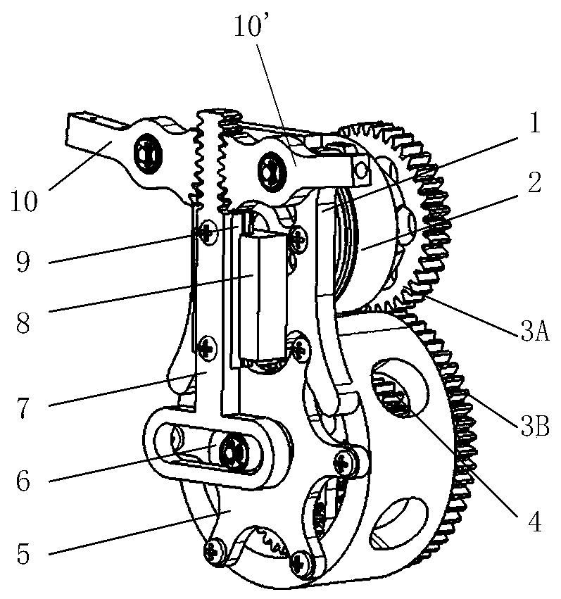
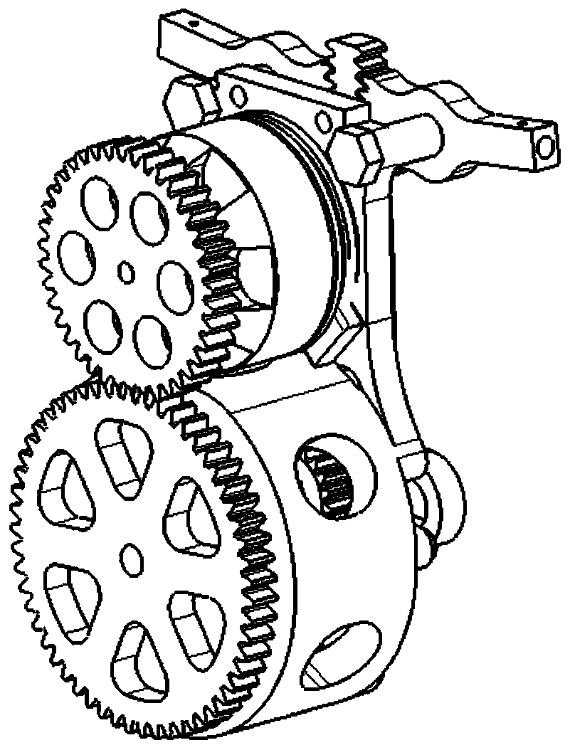
[0031] The invention is based on the rack and pinion flapping wing driving mechanism of the external meshing planetary gear reducer, which includes a frame, a motor, a parallel gear reducer, an external meshing planetary gear reducer and a connecting rod rocker mechanism.

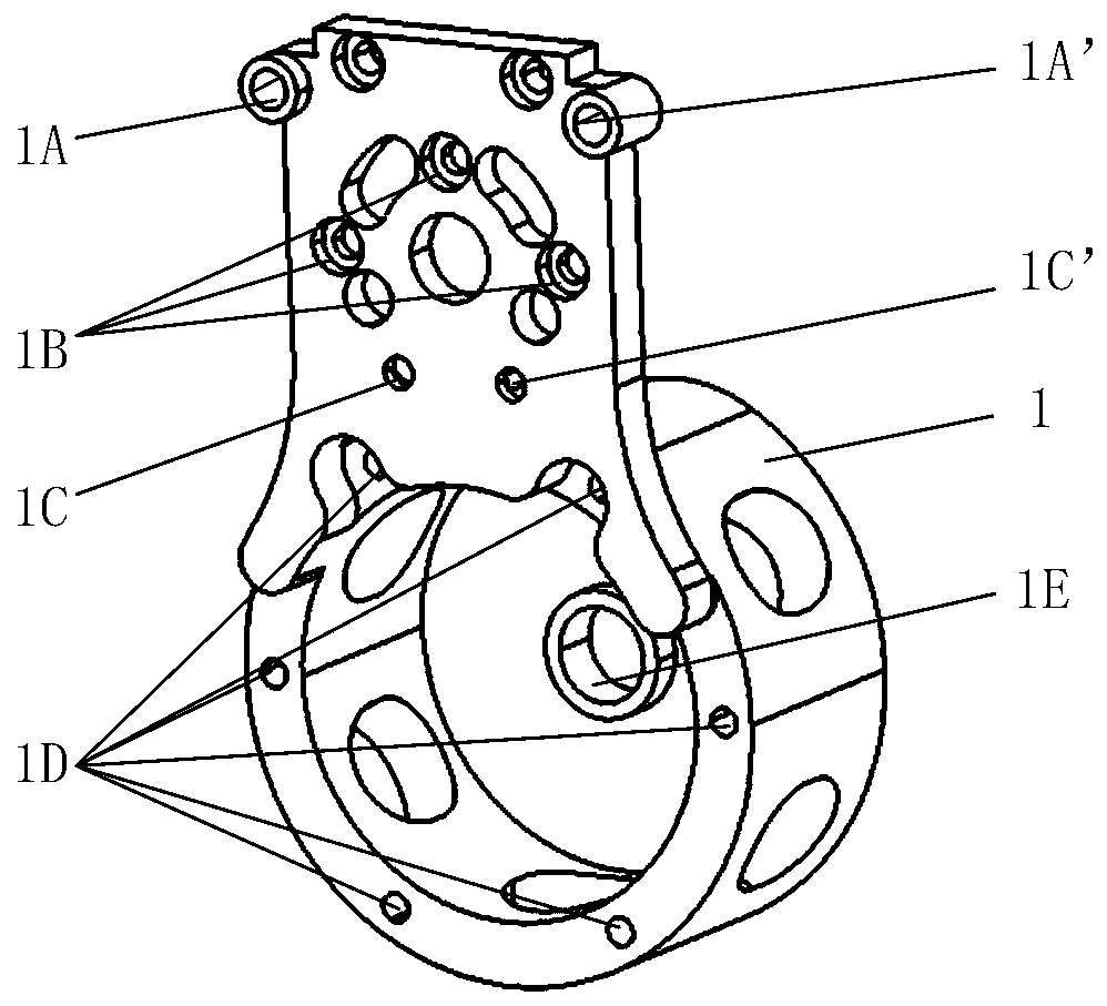
[0032] The frame 1 is left-right symmetrical as a whole, and the direction facing the machine nose is regarded as the front end. Frame 1 is provided with two fixing holes, two rocker shaft holes 1A, 1A', three motor mounting holes 1B, two limit block mounting holes 1C, 1C', and six cover plates from top to bottom. The installation hole 1D and a transmission shaft hole 1E, except the cover plate installation hole, all the holes pass through front and back, and the holes are symmetrically arranged and the axes are all parallel.

[0033] The two fixing holes at the top of the frame 1 are used to install the driving mechanism on the aircraft fuselage by means of threaded connection. The two rocker shaft holes ...


PUM


Abstract

The invention provides a gear rack pair flapping wing driving mechanism based on an externally-meshed planetary gear reducer. The mechanism comprises a machine frame, a motor, a parallel gear reducer,an externally-meshed planetary gear reducer, a cover plate and a gear rack pair connecting rod rocker mechanism, wherein the motor is mounted on the machine frame to drive the parallel gear reducer;the externally-meshed planetary gear reducer is mounted in an internal space formed by the lower half part of the machine frame and the cover plate through a crank shaft hole and a transmission shafthole; the parallel gear reducer drives the externally-meshed planetary gear reducer through a transmission shaft; and the externally-meshed planetary gear reducer is connected with the gear rack pairconnecting rod rocker mechanism through a crank to drive a flapping wing. The externally-meshed planetary gear reducer is utilized to realize compact structure and large reduction ratio, the output torque of the mechanism is improved, the transmission efficiency is high and relatively stable, and the gear rack pair connecting rod rocker arm mechanism is utilized to ensure absolute symmetry of flapping wing movement of the mechanism, so that the flight reliability of an aircraft is greatly improved.

Description

technical field [0001] The invention relates to a flapping-wing driving mechanism, which can be applied to a miniature flapping-wing aircraft. Background technique [0002] Compared with fixed-wing aircraft, micro flapping-wing aircraft can make flight more flexible and efficient by imitating the movement of birds, coupled with its small size and light weight, it can be widely used in various military and civilian fields. Since the flapping wing aircraft mainly generates lift and forward force through the active movement of the wings, how to reasonably design the flapping wing drive mechanism to make the flight aerodynamic efficiency and reliability higher has become the focus of research. [0003] The current flapping wing drive mechanism mainly has the following types: [0004] China Patent Authorization Announcement No. CN102267566A, named as a utility model patent for a continuously variable flapping wing drive mechanism, discloses a stepless speed reduction device that...

Claims


Application Information

Patent Timeline
IPC IPC(8): B64C33/02
Inventor 宋坤苓张玉刚宋笔锋贾洁羽宣建林
Owner NORTHWESTERN POLYTECHNICAL UNIV
Why Eureka
Try Eureka