Chute for concrete pouring of transmission line foundation

A transmission line and concrete technology, which is applied in infrastructure engineering, construction, etc., can solve the problems of low pouring efficiency, long time consumption, single chute body style, etc., and achieve the effect of reducing the frequency of chute transfer, expanding the range, and avoiding rollover

Active Publication Date: 2019-05-24
国网山东省电力公司建设公司 +2
View PDF4 Cites 4 Cited by
  • Summary
  • Abstract
  • Description
  • Claims
  • Application Information

AI Technical Summary

Problems solved by technology

However, at present, the chute body style used by the construction unit of the line project is relatively single, the length of the chute body is fixed, and the chute body is mostly fixed on the commercial concrete truck. This method takes a long time and the pouring efficiency is low

Method used


Image

  • Chute for concrete pouring of transmission line foundation
  • Chute for concrete pouring of transmission line foundation
  • Chute for concrete pouring of transmission line foundation

Examples


Embodiment Construction

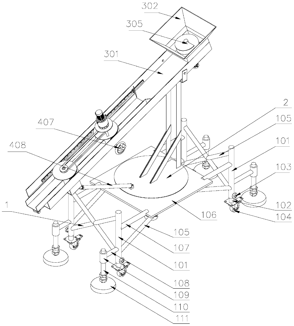
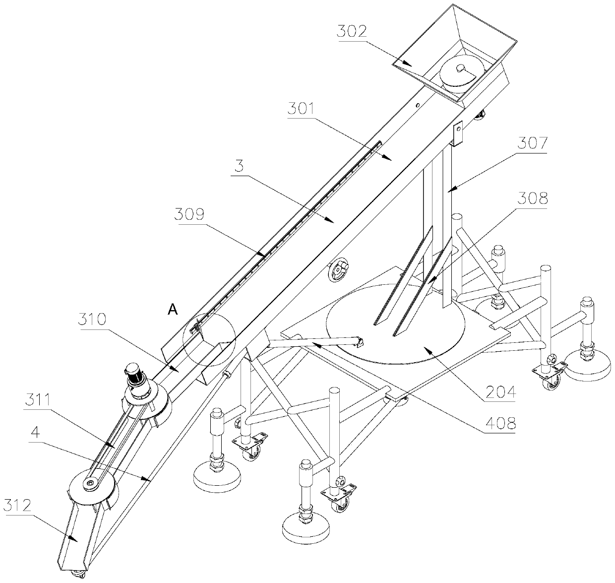
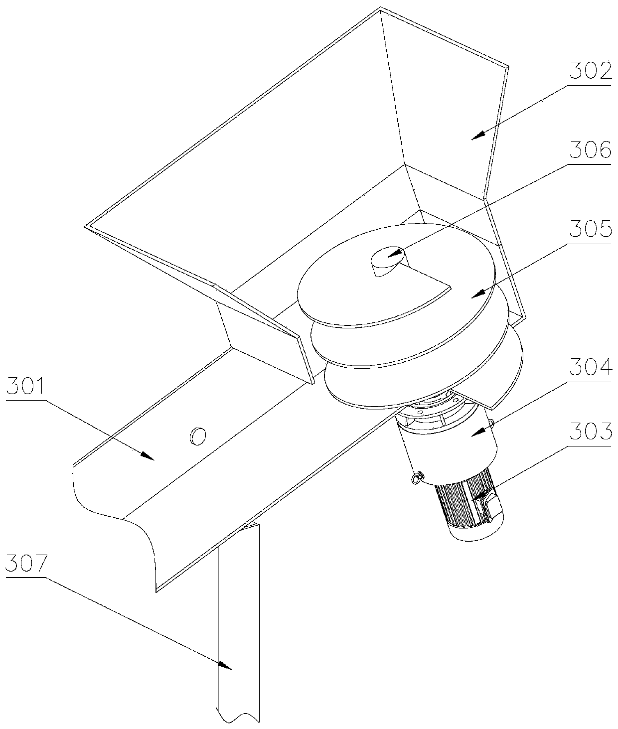
[0039] The following will be combined with Figure 1-9 , clearly and completely describe the technical solutions in the embodiments of the present invention, obviously, the described embodiments are only some of the embodiments of the present invention, not all of them. Based on the embodiments of the present invention, all other embodiments obtained by persons of ordinary skill in the art without making creative efforts belong to the protection scope of the present invention.

[0040] In describing the present invention, it should be understood that the terms "longitudinal", "transverse", "upper", "lower", "front", "rear", "left", "right", "vertical", The orientations or positional relationships indicated by "horizontal", "top", "bottom", "inner", "outer", etc. are based on the orientations or positional relationships shown in the drawings, and are only for the convenience of describing the present invention, rather than indicating or It should not be construed as limiting t...


PUM


Abstract

The invention discloses a chute for concrete pouring of transmission line foundation. The chute is characterized in that a chute body is mounted on the upper portion of a frame, a receiving hopper isarranged at one end of a fixing groove, a first telescopic sleeve is arranged inside the fixing groove in a sleeved manner, a curved plate at one end of a second telescopic sleeve is arranged in a curved plate at one end of the first telescopic groove in a sleeved manner, a curved plate of a third telescopic groove is arranged in a curved plate at the other end of the second telescopic groove in asleeved manner, one end of a first air cylinder is rotatably mounted on the lower portion of the fixing groove through a rotary plate, and the other end of the first air cylinder is connected with ahinged joint on the rotary plate on the lower portion of the third telescopic groove; a buckle plate is connected with a second air cylinder through a base. By the arrangement of the telescopic devices, the chute body can be adjusted in length according the needs of concrete pouring, the first telescopic groove, and the second telescopic groove and the third telescopic groove are connected throughthe curved plates, so that the telescopic grooves can shift on the horizontal direction, the frequency of chute transferring is reduced, and pouring efficiency is improved.

Description

technical field [0001] The invention belongs to the technical field of electric power construction equipment, and in particular relates to a chute for concrete pouring of the foundation of a power transmission line. Background technique [0002] Because there are many transmission line projects at present, the concrete pouring construction of the line foundation is the top priority. Many foundations cannot use concrete pump trucks due to terrain reasons. When the foundation groove is deep or there is a large height difference between the working surface and the concrete, the chute is used. The body slides down the concrete from a high place. This process will not cause segregation of the concrete due to the action of gravity. The slump should be well controlled when pouring the foundation. The free fall height of the concrete should not exceed 2 meters. If the pouring exceeds 2 meters, a chute can be used. Body, chute and other auxiliary tools. However, at present, the chut...

Claims


Application Information

Patent Timeline
Patent Type & Authority Applications(China)
IPC IPC(8): E02D15/02E02D27/42
Inventor 李斌张松孙瑞杜衍乐韩凯郭峰陈永辉汪先涛张兴张震
Owner 国网山东省电力公司建设公司
Why Eureka
Try Eureka