Supercharge Your Innovation With Domain-Expert AI Agents!

Elbow diversion defoaming device applied to high-water-head water supply structure

A technology for defoaming devices and structures, which can be used in the configuration of water supply devices and water supply pools, water conservation, etc., and can solve problems such as large drop, entry, and aggravated water pressure fluctuations in water supply pipes

Pending Publication Date: 2019-05-24
GUANGDONG RES INST OF WATER RESOURCES & HYDROPOWER
View PDF0 Cites 0 Cited by
  • Summary
  • Abstract
  • Description
  • Claims
  • Application Information

AI Technical Summary

Problems solved by technology

[0003] In the prior art, the technical defect of the general high-level pool is that the drop from the annular overflow weir to the lowest operating water level is large, which will cause a large number of air bubbles to be mixed into the water body, and the air bubbles will enter the outlet pipe with the water flow, which intensifies the The fluctuation range of the water pressure of the water supply pipeline is very unfavorable for the safety of the long-distance water supply pipeline

Method used


Image

  • Elbow diversion defoaming device applied to high-water-head water supply structure
  • Elbow diversion defoaming device applied to high-water-head water supply structure
  • Elbow diversion defoaming device applied to high-water-head water supply structure

Examples


Embodiment Construction

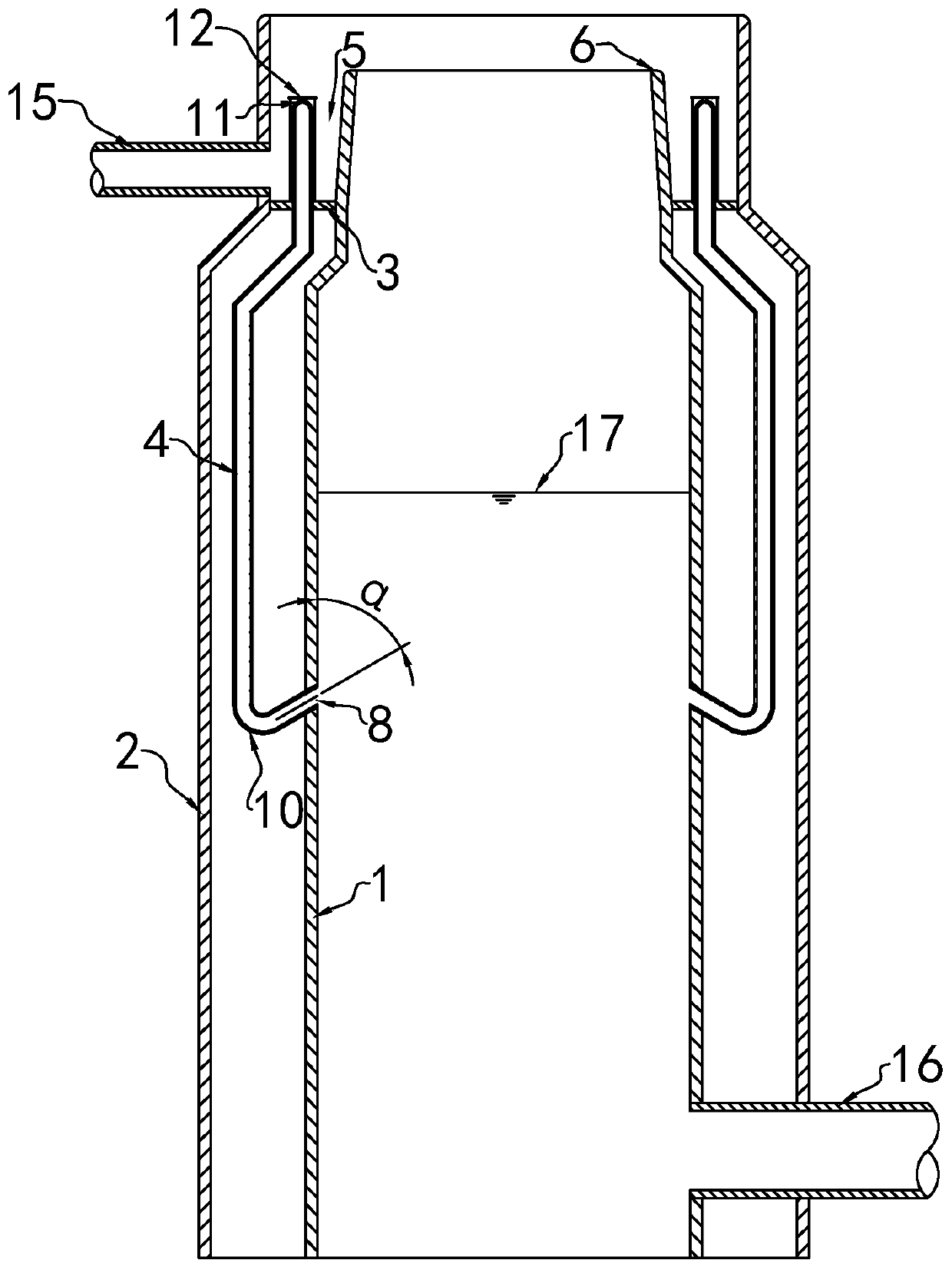
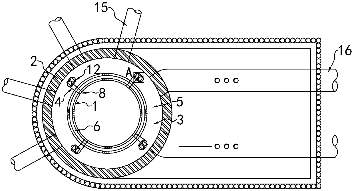
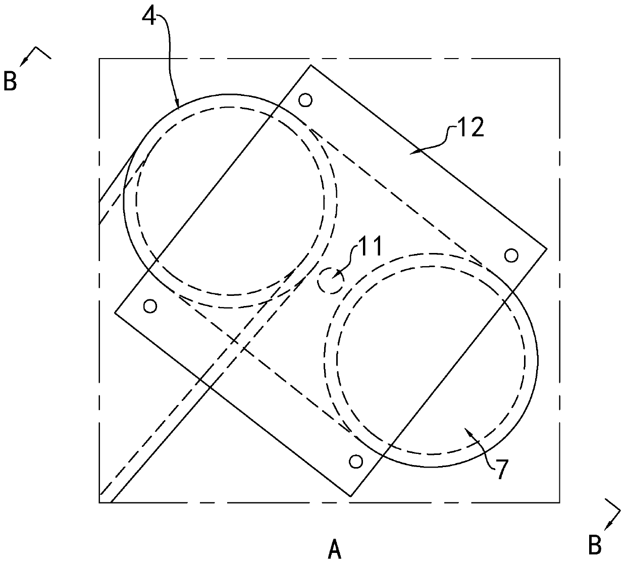
[0021] refer to Figures 1 to 4 , an elbow diversion and defoaming device applied to high water head water supply structures, comprising an inner well 1, an outer well 2, a partition 3 and four overflow pipes 4, the outer well 2 is nested outside the inner well 1, and the outer well The top of 2 is higher than the inner well 1, and the partition 3 is connected with the outer wall of the inner well 1 and the inner wall of the outer well 2 respectively to form an overflow groove 5, and the top of the inner well 1 is higher than the partition 3 and forms an overflow weir 6, One end of the overflow pipe 4 is provided with a first nozzle 7 in the overflow tank 5, and the other end of the overflow pipe 4 communicates with the inner well 1 to form a second nozzle 8, and the first nozzle 7 is higher than the second nozzle 8. The overflow pipe 4 is bent in the overflow tank 5 to form a first bent portion 9 , and the first bent portion 9 is higher than the first nozzle 7 .

[0022] The...


PUM


Abstract

The invention discloses an elbow diversion defoaming device applied to a high-water-head water supply structure. The elbow diversion defoaming device comprises an inner well, an outer well, a partition and a plurality of overflow pipes, one end of each overflow pipe is provided with a first pipe orifice in an overflow groove while the other end of the same is communicated with the inner well to form a second pipe orifice, each pipe orifice is higher than the corresponding second pipe orifice, and each overflow pipe is bent in the overflow groove to form a first bent portion which is higher than the corresponding first pipe orifice. The elbow diversion defoaming device has the advantages that the overflow pipes can divert water flow passing an overflow weir, and aerification can be better inhibited by means of injecting the water flow into the inner well through the overflow pipes than a mode of allowing the water flow to fall into the inner well through the overflow weir; each first bent portion is higher than the corresponding first pipe orifice, so that water can be guided into the inner well through the overflow pipes only after depth of the water in the overflow groove reachesa certain degree, air suction vortex caused by the fact that water depth in the overflow groove is too shallow can be prevented, reducing of aerification caused during drainage of the overflow pipes is facilitated, and reducing of vibration of the whole elbow diversion defoaming device is facilitated. The elbow diversion defoaming device relates to waterwork.

Description

technical field [0001] The invention relates to hydraulic structures, in particular to an elbow diversion defoaming device applied to high water head water supply structures. Background technique [0002] The high-level pool is a hydraulic structure specially used for long-distance water supply. Its main function is to stabilize the color temperature and tail water level of the pump station, and to adjust the water level in the well to ensure the stability of the water supply head. The high-level pool is usually designed in a cylindrical shape. After the water enters from the water inlet pipe, it first passes through the annular overflow weir, and then overflows like a well. [0003] In the prior art, the technical defect of the general high-level pool is that the drop from the annular overflow weir to the lowest operating water level is large, which will cause a large number of air bubbles to be mixed into the water body, and the air bubbles will enter the outlet pipe with ...

Claims


Application Information

Patent Timeline
IPC IPC(8): E03B11/12E03B7/07
CPCE03B11/12E03B7/07E03B7/074B01D19/0042Y02A20/00B01D19/02Y10S435/812
Inventor 黄本胜刘达邱静李明谭超郭磊
Owner GUANGDONG RES INST OF WATER RESOURCES & HYDROPOWER
Features
  • R&D
  • Intellectual Property
  • Life Sciences
  • Materials
  • Tech Scout
  • Unparalleled Data Quality
  • Higher Quality Content
  • 60% Fewer Hallucinations
Learn More