Eureka AIR delivers breakthrough ideas for toughest innovation challenges, trusted by R&D personnel around the world.

Multi-channel ejector for gas cooker, burner and gas cooker

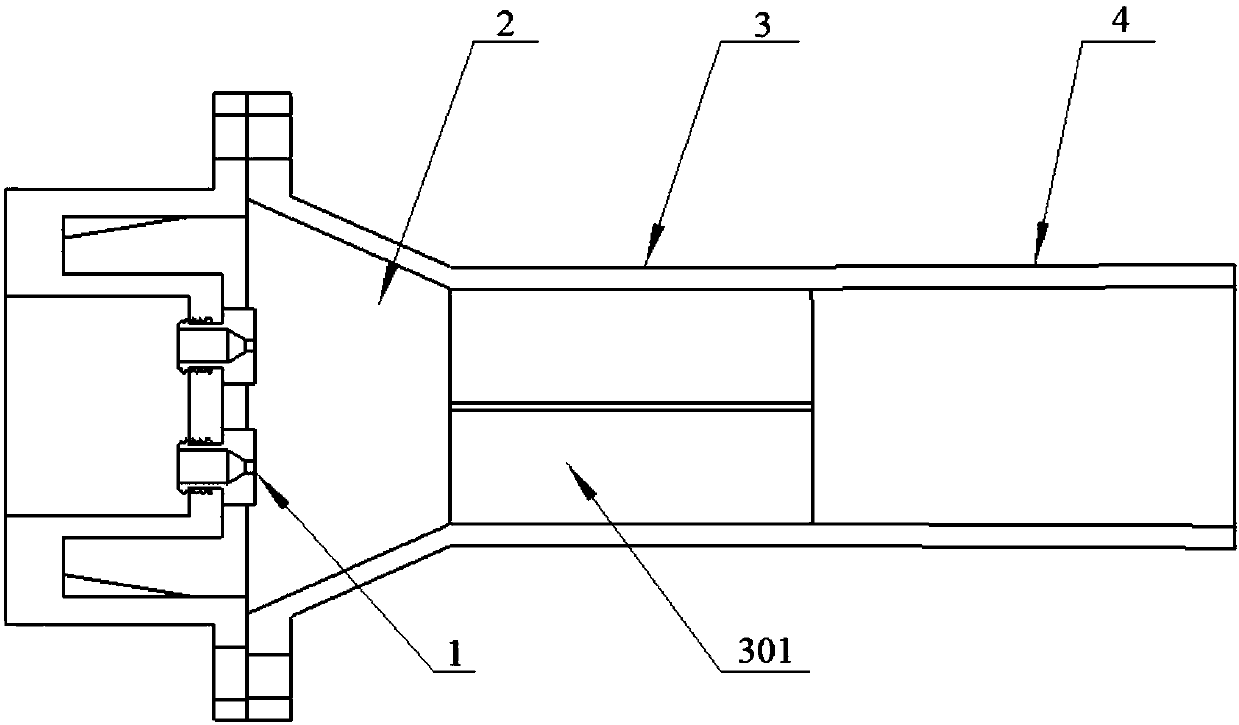
A gas cooker and ejector technology, which is applied to gas fuel burners, burners, combustion methods and other directions, can solve problems such as poor ejection effect of the ejector, and achieves improved ejection capability, improved mixing effect, and improved mixing effect. uniform effect

Pending Publication Date: 2019-05-24
VATTI CORP LTD
View PDF0 Cites 3 Cited by
  • Summary
  • Abstract
  • Description
  • Claims
  • Application Information

AI Technical Summary

Problems solved by technology

[0004] The purpose of the present invention is to provide a multi-channel injector, a burner and a gas cooker for gas cookers, so as to solve the problem of poor ejection effect of the injector in the prior art

Method used


Image

  • Multi-channel ejector for gas cooker, burner and gas cooker
  • Multi-channel ejector for gas cooker, burner and gas cooker
  • Multi-channel ejector for gas cooker, burner and gas cooker

Examples


Embodiment 1

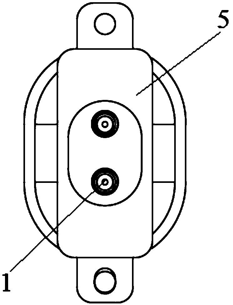
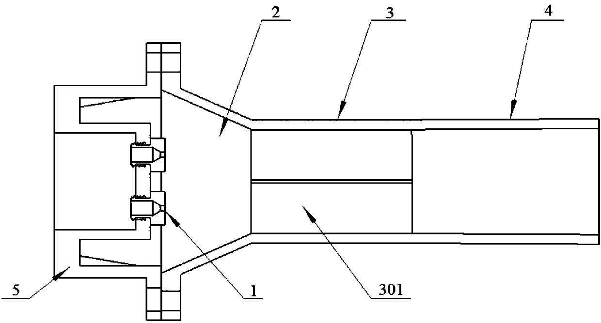
[0025] Embodiment 1: as image 3 As shown, the mixing tube 3 is composed of two sub-mixing tubes 301 , correspondingly, two nozzles 1 are arranged on the nozzle mounting base 5 , and each nozzle 1 is set corresponding to the position of a sub-mixing tube 301 .

Embodiment 2

[0026] Embodiment 2: as Figure 4 As shown, the mixing tube 3 is composed of three sub-mixing tubes 301 , correspondingly, three nozzles 1 are arranged on the nozzle mounting base 5 , and each nozzle 1 is set corresponding to the position of a sub-mixing tube 301 .

[0027] The second technical scheme provided by the present invention is:

[0028] A burner comprising a burner head, a heating body and a gas distribution plate, the heating body is located in the gas distribution plate, the burner head is located below the gas distribution plate, an ejector is arranged on the burner head, The structure of the ejector is: as figure 1 As shown, it includes nozzles 1 and ejector pipes arranged in sequence along the direction of gas flow, and at least two nozzles 1 are arranged and docked with the ejector pipes; The suction shrinkage tube 2, the mixing tube 3 and the diffuser tube 4 are composed, the mixing tube 3 is composed of the same number of sub-mixing tubes 301 as the number...


PUM


Abstract

The invention discloses a multi-channel ejector for a gas cooker, and provides a burner and a gas cooker. The multi-channel ejector for the gas cooker comprises at least two nozzles and an ejecting pipe, wherein the nozzles and the ejecting pipe are sequentially arranged along the air flow direction; the nozzles are in butt joint with the ejecting pipe; the ejecting pipe is composed of a suction shrink tube, a mixing pipe and a diffuser pipe which are sequentially connected according to the air flow direction and changes of the cross sections; the mixing pipe is composed of branch mixing pipeswith same quantity of nozzles; and each nozzle corresponds to one branch mixing pipe. According to the multi-channel ejector for a gas cooker, the mixing pipe is divided into multiple branch mixing pipes, multiple nozzles are arranged, and each of the nozzles corresponds to one branch mixing pipe, so that the gas and the air are mixed more uniformly, the mixing effect of the gas and the air is improved, and the ejection ability is improved as well.

Description

technical field [0001] The invention belongs to the technical field of gas cooker devices, and in particular relates to a multi-channel ejector, a burner and a gas cooker for a gas cooker. Background technique [0002] The ejector is an important part of the gas cooker. Its function is to fully mix the gas and air according to a certain ratio, so as to make the gas burn more fully, and the primary air coefficient is a key parameter to measure its ejection ability; The injector generally includes a nozzle and an ejector tube, wherein the ejector tube is divided into a suction contraction tube, a mixing tube and a diffuser tube along the gas flow direction according to the change of the cross-sectional area. [0003] In the existing ejector, the mixing tube in the ejecting tube is an integral circular channel, although this structure can be changed by changing the diameter and length of the mixing tube and the size of other components, or by setting the nozzle on the nozzle A...

Claims


Application Information

Patent Timeline
Patent Type & Authority Applications(China)
IPC IPC(8): F23D14/04F23D14/58F23D14/64F24C3/08
Inventor 罗峰李成信易洪斌潘叶江
Owner VATTI CORP LTD
Why Eureka
Eureka Blog
Learn More