Gyroscope structure

A gyroscope and mass block technology, applied in gyroscope/steering sensing equipment, gyro effect for speed measurement, instruments, etc., to achieve the effect of convenient design, improved sensitivity and accuracy

Pending Publication Date: 2019-05-24
QST CORP
View PDF4 Cites 8 Cited by
  • Summary
  • Abstract
  • Description
  • Claims
  • Application Information

AI Technical Summary

Problems solved by technology

[0004] The performance of the gyroscope in the prior art still needs to be further improved

Method used


Image

  • Gyroscope structure
  • Gyroscope structure
  • Gyroscope structure

Examples


Embodiment Construction

[0028] The specific implementation of the gyroscope structure provided by the present invention will be described in detail below in conjunction with the accompanying drawings.

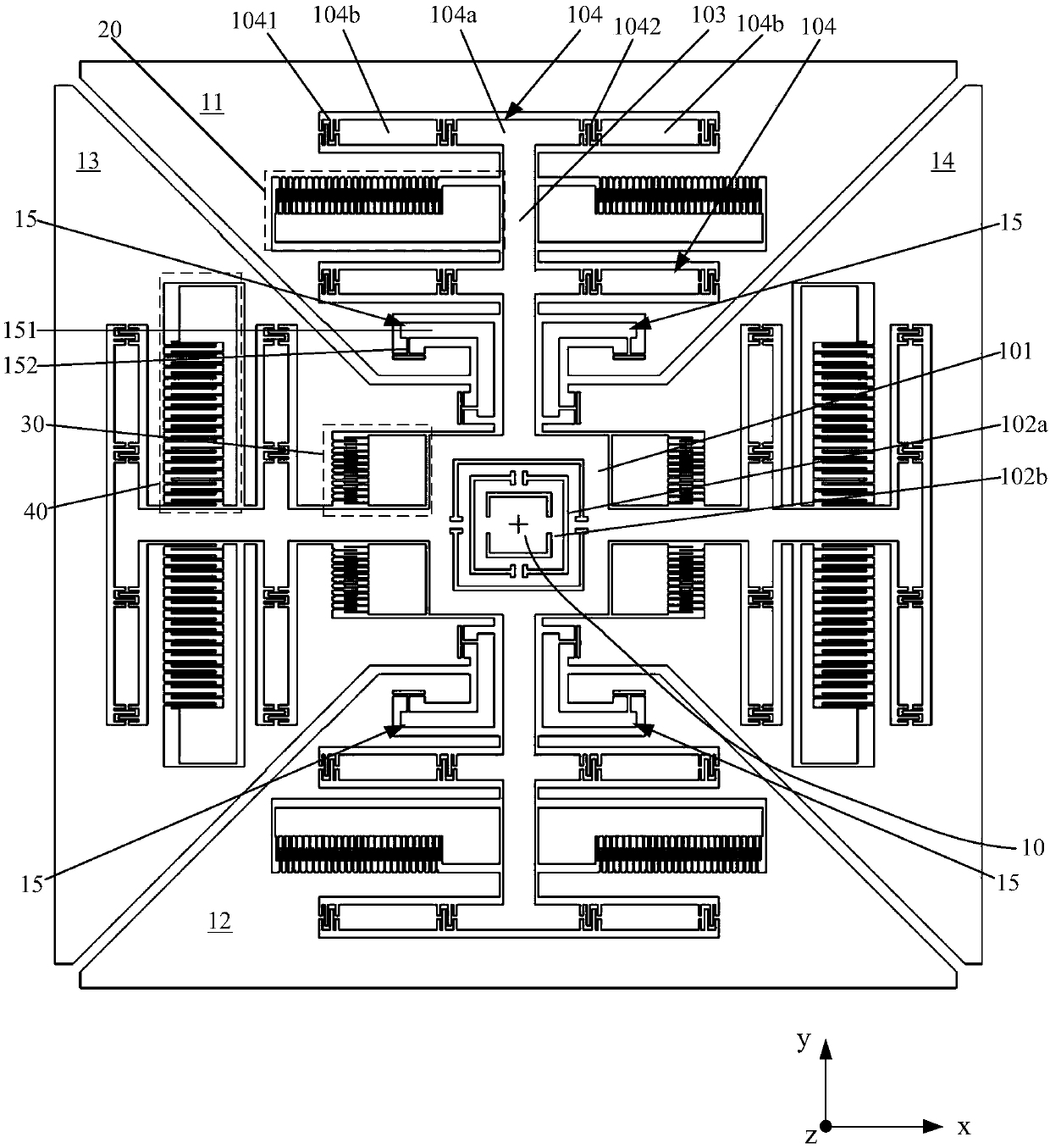
[0029] Please refer to figure 1 , is a structural schematic diagram of a gyroscope structure according to a specific embodiment of the present invention.

[0030] The gyroscope includes: a substrate (not shown in the figure), an anchor point 10 fixed on the substrate, a plurality of mass blocks suspended on the substrate around the anchor point, including: a first mass Block 11, second mass block 12, third mass block 13 and fourth mass block 14, the plurality of mass blocks are respectively connected to the anchor point 10 through elastic connection components; the first mass block 11, the second mass block The mass blocks 12 are arranged oppositely in the first direction, and are used to make the first mass block 11 and the second mass block 12 perform translational reciprocating motion along the fi...


PUM


Abstract

Disclosed is a gyroscope structure. The gyroscope structure includes a substrate, an anchor point fixed on the substrate and multiple mass blocks arranged around the anchor point and suspended on thesubstrate. The multiple mass blocks include a first mass block, a second mass block, a third mass block and a fourth mass block. The multiple mass blocks are connected to the anchor points through elastic connecting components. The first mass block and the second mass block are oppositely arranged in a first direction so as to make the first mass block and the second mass block perform a translational reciprocating motion in the first direction under power drive. The third mass block and the fourth mass block are oppositely arranged in a second direction. The first mass block and the second mass block are connected to each other through a coupling component and the third mass block and the fourth mass block are connected to each other through a coupling component so as to drive the third mass block and the fourth mass block to perform a translational reciprocating motion in the second direction when the first mass block and the second mass block perform the translational reciprocatingmotion in the first direction. The second direction and the first direction are perpendicular to each other and are in the same plane. The accuracy and sensitivity of a gyroscope are improved.

Description

technical field [0001] The invention relates to the field of micro-electromechanical technology, in particular to a gyroscope structure. Background technique [0002] The MEMS (Micro Electro Mechanical System, Micro Electro Mechanical System) gyroscope utilizes the Coriolis force (Coriolis force, also called Coriolis force) phenomenon. The Coriolis force is a description of the offset of the linear motion of a particle in a rotating system due to inertia relative to the linear motion of the rotating system. The Coriolis force comes from the inertia of the object's motion. The particle moving in a straight line in the rotating system has a tendency to continue moving along the original direction of motion due to the inertia. However, because the system itself is rotating, in the After a period of movement, the position of the particle in the system will change, and the direction of its original movement trend will deviate to a certain extent if it is observed from the perspe...

Claims


Application Information

Patent Timeline
Patent Type & Authority Applications(China)
IPC IPC(8): G01C19/5656
Inventor 裘进郭慧芳
Owner QST CORP
Why Eureka
Try Eureka