Eureka AIR delivers breakthrough ideas for toughest innovation challenges, trusted by R&D personnel around the world.

Linear motor system

A linear motor, electromagnetic coil technology, applied in the direction of propulsion system, electrical components, electromechanical devices, etc., can solve problems such as flexibility limitation, and achieve the effect of reducing effect and interference, low cost and low inductance

Inactive Publication Date: 2019-05-24
SCHNEIDER ELECTRIC IND SAS
View PDF6 Cites 2 Cited by
  • Summary
  • Abstract
  • Description
  • Claims
  • Application Information

AI Technical Summary

Problems solved by technology

The flexibility in arranging a plurality of stator elements with longitudinal flux is thus limited, thereby restricting the design of the desired movement path of the rotor and placing higher demands on manufacturing accuracy

Method used


Image

  • Linear motor system
  • Linear motor system
  • Linear motor system

Examples


Embodiment Construction

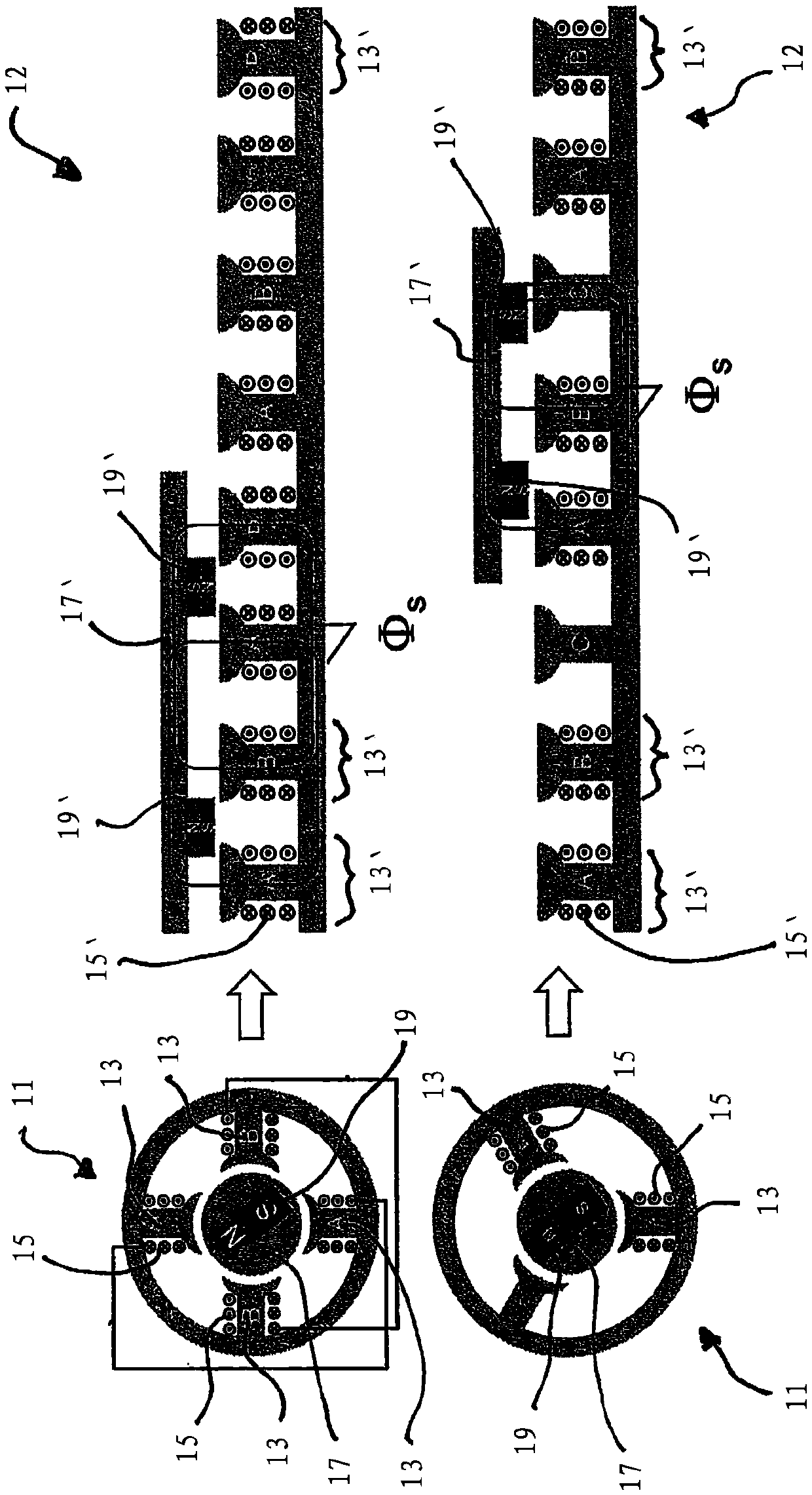
[0049] figure 1 On the left are shown two conventional electric machines 11 , each comprising four or three stator elements 13 with respective electromagnetic coils 15 and a rotor 17 with permanent magnets 19 . A magnetic flux in the electric machine 11 is formed by the magnetic coil 15 when current flows through it. The magnetic flux interacts with the permanent magnets 19 of the rotor 17 and thereby causes the rotor 17 to rotate.

[0050] exist figure 1 On the right, a conventional electric motor 12 is respectively formed as a linear motor system 12 according to the prior art. The stator element 13' of the linear motor system 12 corresponds to the stator element 13 of the motor 11, and the rotor 17' of the linear motor system 12 with two permanent magnets 19' corresponds to the rotor 17 of the motor 11 with permanent magnets 19, respectively. The stator elements 13 of the electric motor 11 thus spread out to a certain extent in a linear direction, and the stator elements ...


PUM


Abstract

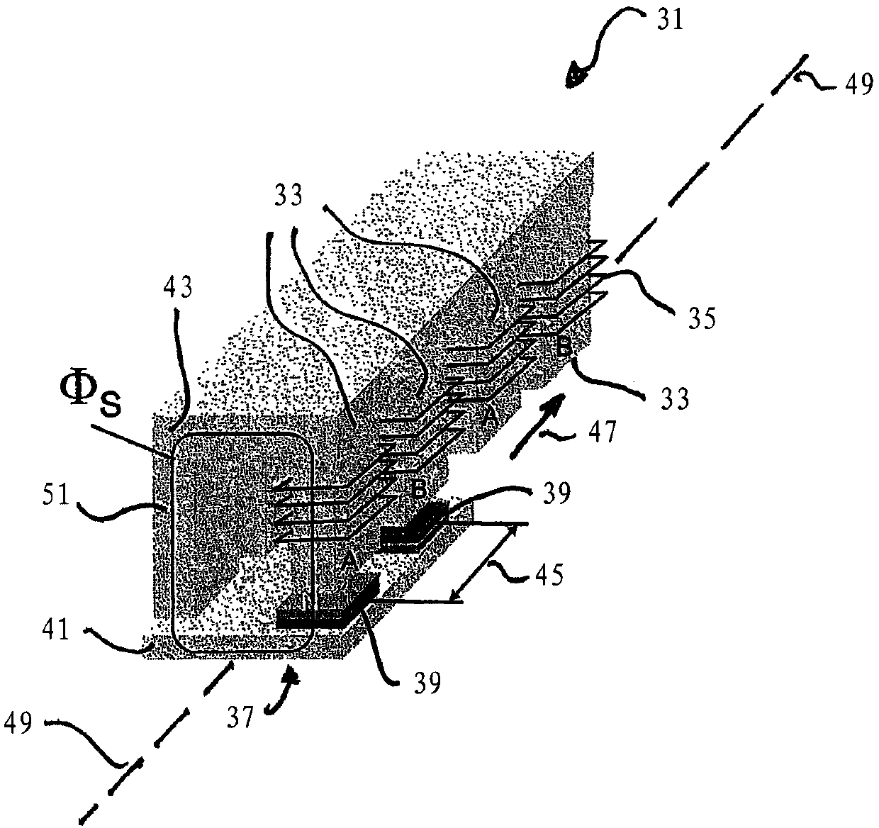
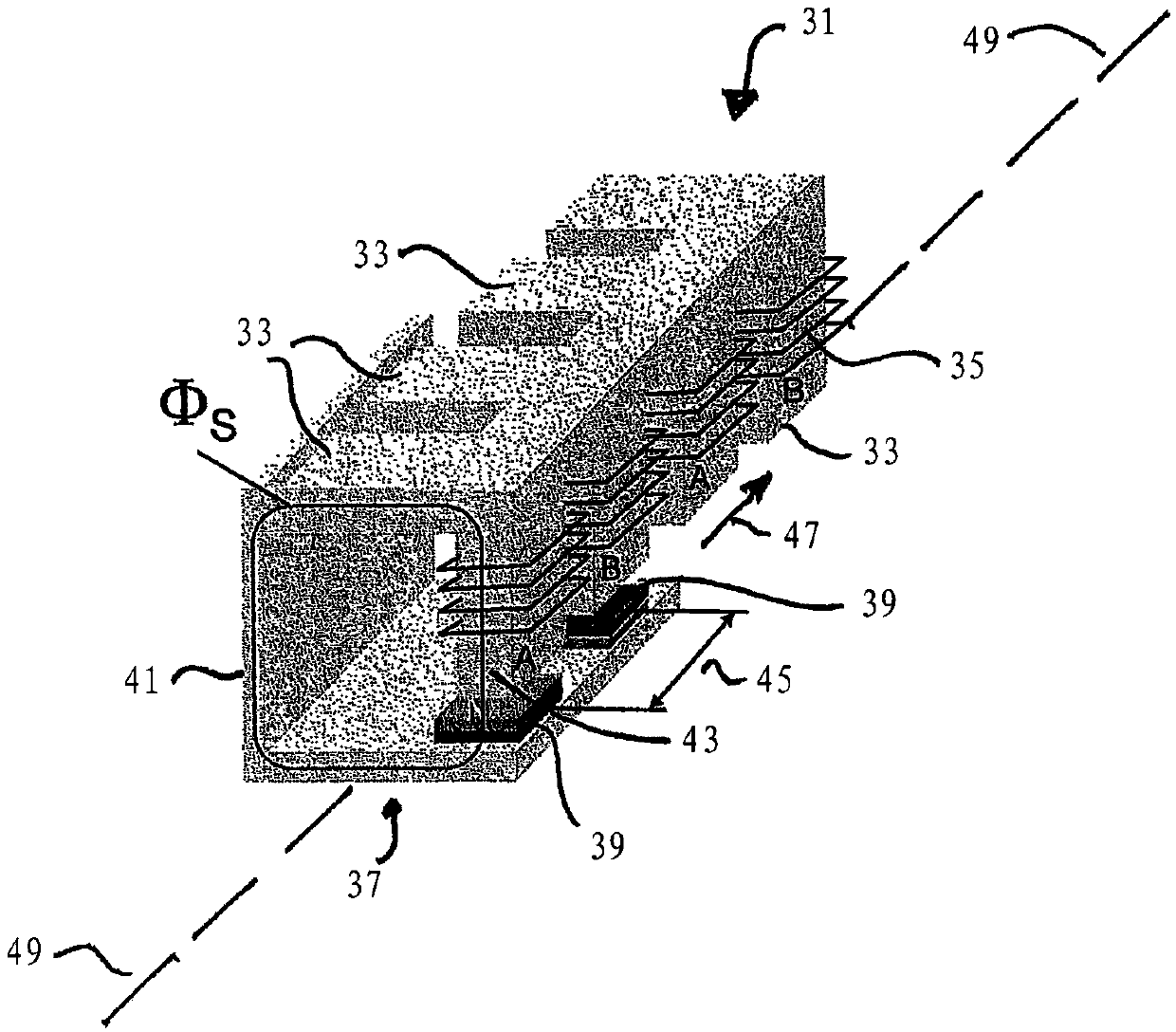
The present invention relates to a linear motor system comprising a plurality of stator elements and at least one rotor, each having an electromagnetic coil forming a magnetic flux in each stator element, the rotor has at least one magnet element, and the magnet element interacts with the electromagnetic coil of the stator element. The rotor can be moved relative to the stator element in the direction of movement by activation of the at least one stator element. The magnetic flux extends at least partially laterally in the at least one stator element based on the direction of movement of the rotor. The linear motor system is designed to activate the electromagnetic coils of the stator elements individually and independently of one another.

Description

technical field [0001] The invention relates to a linear motor system with a plurality of stator elements each comprising electromagnetic coils and at least one rotor, the rotor having magnet elements which interact with the electromagnetic coils of the stator elements , and the rotor is movable relative to the stator element in the direction of motion by activation of at least one suitable stator element. Background technique [0002] Known linear motor systems are derived from conventional electric motors which have a rotor with permanent magnets which are arranged inside stator elements each with an electromagnetic coil. The rotor of such an electric machine is caused to rotate by activating the corresponding solenoid coils, ie by current flowing through the solenoid coils. [0003] In known linear motor systems, the stator elements of a conventional electric motor are so to speak unrolled and arranged linearly one behind the other. The rotor that can move along the pre...

Claims


Application Information

Patent Timeline
IPC IPC(8): H02K16/00H02K41/02
CPCH02K41/031H02K2201/12H02K2213/12
Inventor W.布兰德斯塔特
Owner SCHNEIDER ELECTRIC IND SAS
Why Eureka
Eureka Blog
Learn More