Supercharge Your Innovation With Domain-Expert AI Agents!

Crop straw pullout mechanism and method

A technology for crop straws and racks, which is applied to crop straw pulling mechanisms and the field of pulling them, can solve the problems of low resilience of green straws and fine straws, missed pulling and breaking of straws, inability to apply sufficient friction force to the crop straws, and the like. Achieve the effect of large contact area and long contact time

Active Publication Date: 2019-05-28
FUJIAN YONGSHUN MACHINERY CO LTD
View PDF6 Cites 0 Cited by
  • Summary
  • Abstract
  • Description
  • Claims
  • Application Information

AI Technical Summary

Problems solved by technology

[0003] However, after testing, the above-mentioned combined mechanism for removing and cutting crop stalks has the following problems: due to the action of the stalk-pulling rotor, when the stalks are attached to the outer edge of the stalk-pulling rotor, the return of green straw and fine straw with a low lignification level The elastic force is small, and it is impossible to form enough friction between the outer edge of the stalk pulling rotor and the straw, so that the stalk pulling rotor cannot apply enough friction force to the crop stalks, that is, the friction force is smaller than the resident force of the crop stalks, resulting in missing straw pulling And the phenomenon of pulling out is serious

Method used


Image

  • Crop straw pullout mechanism and method
  • Crop straw pullout mechanism and method
  • Crop straw pullout mechanism and method

Examples


Embodiment 1

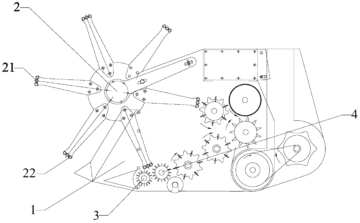
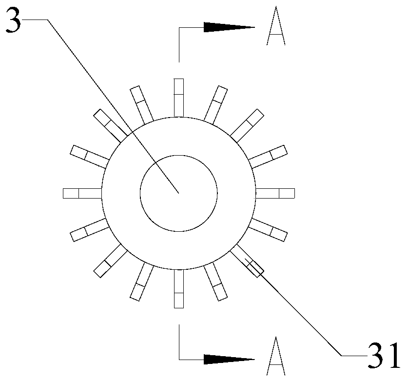
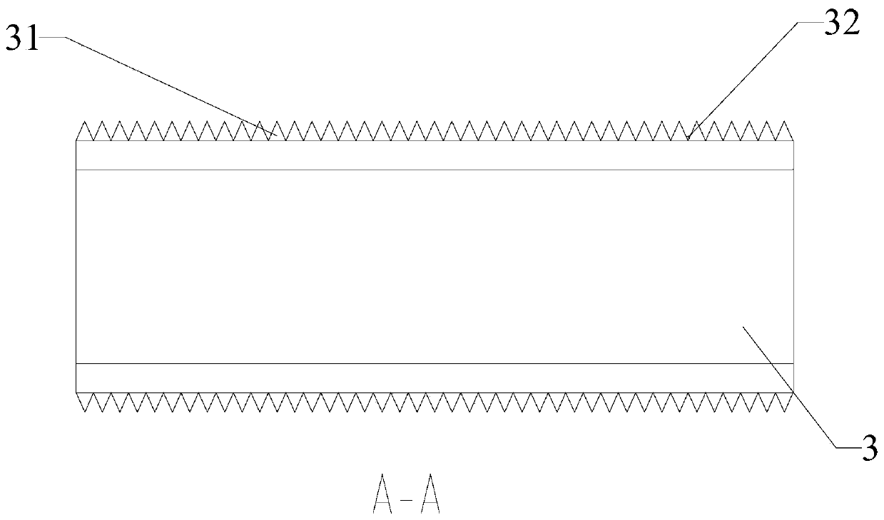
[0043] A mechanism for removing crop stalks, comprising a stalk-pulling rotor 2 and a first stalk-pulling rotor 3 arranged on a frame 1, the turning directions of the stalk-pulling rotor 2 and the first stalk-pulling rotor 3 are opposite; the stalk-pulling rotor 2 The rotation axis center of the first stalk pulling rotor 3 is set at the upper front of the frame 1 relative to the rotation axis center of the first stalk pulling rotor 3; a plurality of stalk pulling racks 31 are arranged on the outer edge of the first stalk pulling rotor 3, so that The tooth root depth of the stalk pulling rack 31 is less than twice the diameter of the stalk of the crop stalk; diameter of.

[0044] The outer edge of the circumference of the stalk pulling rotor 2 is provided with a plurality of stalk pulling grid bars 21 , and the outer edge of the stalk pulling grid bars 21 is arc-shaped with the rotation axis of the stalk pulling rotor 2 . The number of the stalk pulling racks 31 is more than 1...

Embodiment 2

[0046] A crop stalk removal mechanism described in Embodiment 1, wherein a plurality of stalk pulling grids 21 are arranged on the outer edge of the circumference of the stalk pulling rotor 2, and the stalk pulling grids 21 include one stalk pulling roller arranged side by side 22. The centers of the stalk pulling rollers 22 are distributed on the same circle with the rotation axis of the stalk pulling rotor 2 as the center.

Embodiment 3

[0048] A crop stalk removal mechanism according to Embodiment 2, wherein a plurality of stalk pulling grids 21 are arranged on the outer edge of the circumference of the stalk pulling rotor 2, and the stalk pulling grids 21 include three stalk pulling rollers arranged side by side twenty two.


PUM


Abstract

The invention relates to the field of agricultural machinery, in particular to a crop straw pullout mechanism. Through the outer edge of a straw shifting rotor and resilience force of crop straw, thecrop straw is shifted into a gap between a first straw shifting rotor and the straw shifting rotor and covers toothed grooves of the first straw shifting rotor in a pressing mode to enable the toothedgrooves to form friction force and enable the crop straw to adhere to the first straw shifting rotor in a winding mode to form a wrap angle; and under the joint effect of the friction force generatedby press covering and stationing force of roots of the straw to the ground, the crop straw and a straw pull rack of the first straw shifting rotor have the lager contact area and the longer contact time, the crop straw with the small resilience force also can force the large friction force together with the straw shifting rotor and the first straw shifting rotor, and thus it is guaranteed that the crop straw is completely pulled out and conveyed rearwards.

Description

technical field [0001] The invention relates to the field of agricultural machinery, in particular to a mechanism for removing crop stalks and a method for removing them. Background technique [0002] The Chinese patent with the publication number CN 109121677 A discloses a combined mechanism for pulling out and cutting crop stalks. The crop stalks are uprooted by the stalk pulling mechanism, and then cut off by the cutting stalk mechanism. The crop stalks are cut into sections for recycling. . [0003] However, after testing, the above-mentioned combined mechanism for removing and cutting crop stalks has the following problems: due to the action of the stalk-pulling rotor, when the stalks are attached to the outer edge of the stalk-pulling rotor, the return of green straw and fine straw with a low lignification level The elastic force is small, and it is impossible to form enough friction between the outer edge of the stalk pulling rotor and the straw, so that the stalk pu...

Claims


Application Information

Patent Timeline
IPC IPC(8): A01D45/00
Inventor 张培坤王又沐
Owner FUJIAN YONGSHUN MACHINERY CO LTD
Features
  • R&D
  • Intellectual Property
  • Life Sciences
  • Materials
  • Tech Scout
  • Unparalleled Data Quality
  • Higher Quality Content
  • 60% Fewer Hallucinations
Learn More