Supercharge Your Innovation With Domain-Expert AI Agents!

Universal type cylindrical workpiece machining tooling

A general-purpose, cylindrical technology, applied in metal processing equipment, metal processing mechanical parts, positioning devices, etc., can solve the problems of increased processing costs, poor generality of processing tooling, etc., to improve work efficiency, good versatility, and reduce processing. cost effect

Inactive Publication Date: 2019-05-28
杭州联德精密机械股份有限公司
View PDF8 Cites 2 Cited by
  • Summary
  • Abstract
  • Description
  • Claims
  • Application Information

AI Technical Summary

Problems solved by technology

[0003] The invention overcomes the disadvantages of the poor versatility of the cylindrical workpiece processing tool, which is only suitable for one processing technology of one type of workpiece, which increases the processing cost, and provides a general-purpose cylindrical workpiece processing tool, which has good versatility, The processing technology with vertical lathe process and without vertical lathe process is suitable for various types of cylindrical workpieces, which is beneficial to reduce processing costs and improve work efficiency

Method used


Image

  • Universal type cylindrical workpiece machining tooling
  • Universal type cylindrical workpiece machining tooling
  • Universal type cylindrical workpiece machining tooling

Examples


Embodiment 1

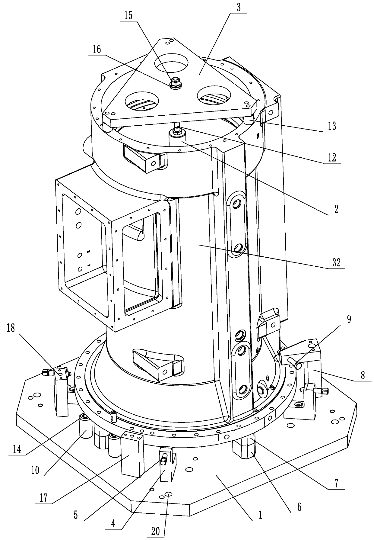
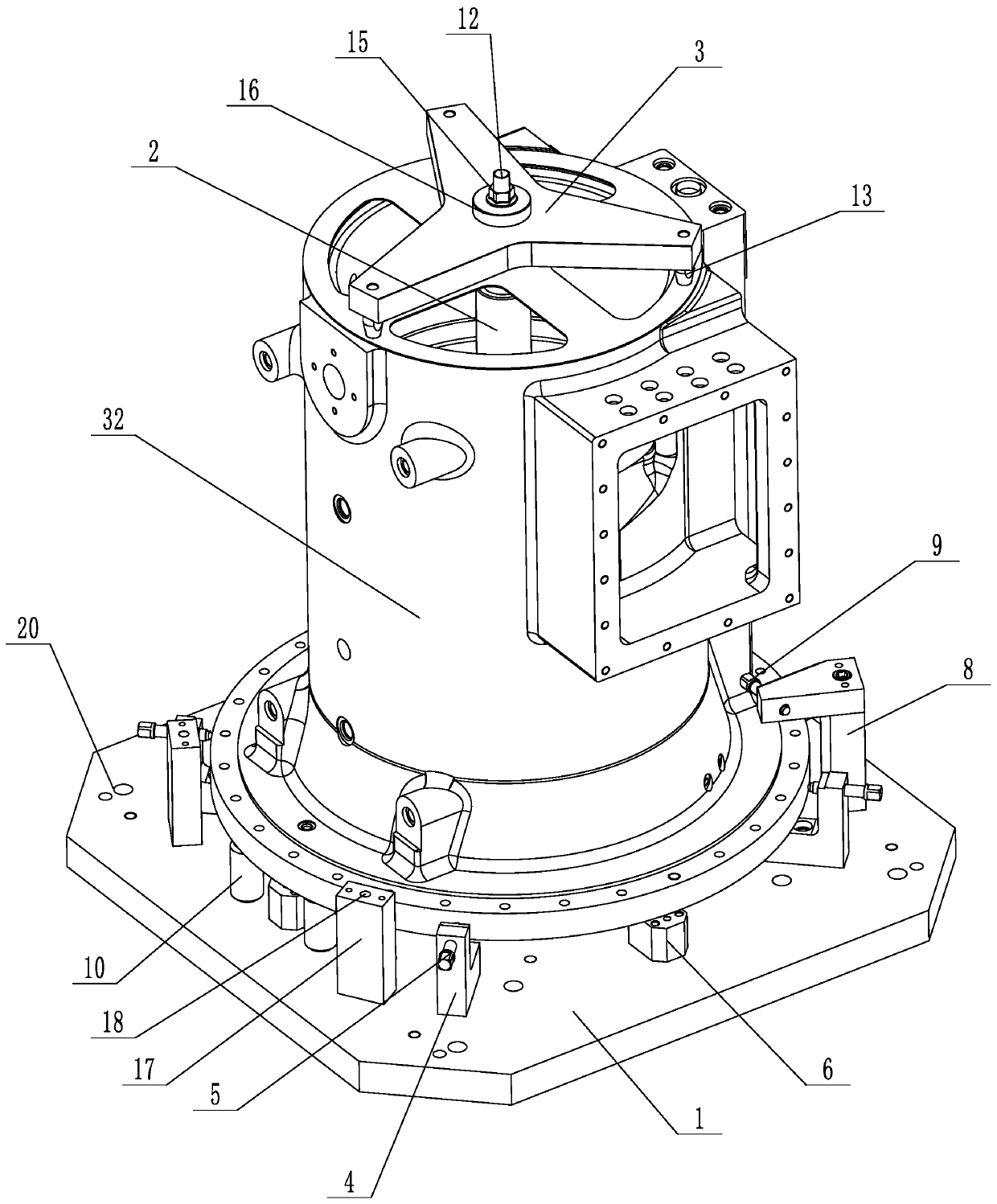
[0027] Example 1: A universal cylindrical workpiece processing tool (see attached figure 1 , attached figure 2 ), including the base 1, the positioning column 2, the pressure plate 3, the lower end of the positioning column is connected to the base, the base is rectangular, the corners of the base are installed with side top blocks 4, and the side top blocks are connected with the thread set radially toward the positioning column The top rod 5, the positioning support base 6 is installed between the adjacent top blocks on both sides, the support block 7 is detachably installed on the positioning support base, and the positioning support block on one side of the base is installed with an inverted L-shaped positioning top block on both sides. 8. The positioning top block is threadedly connected to the positioning top rod 9, and the two positioning top rods are set opposite each other. The positioning support seat on the other opposite side of the base is equipped with support c...

Embodiment 2

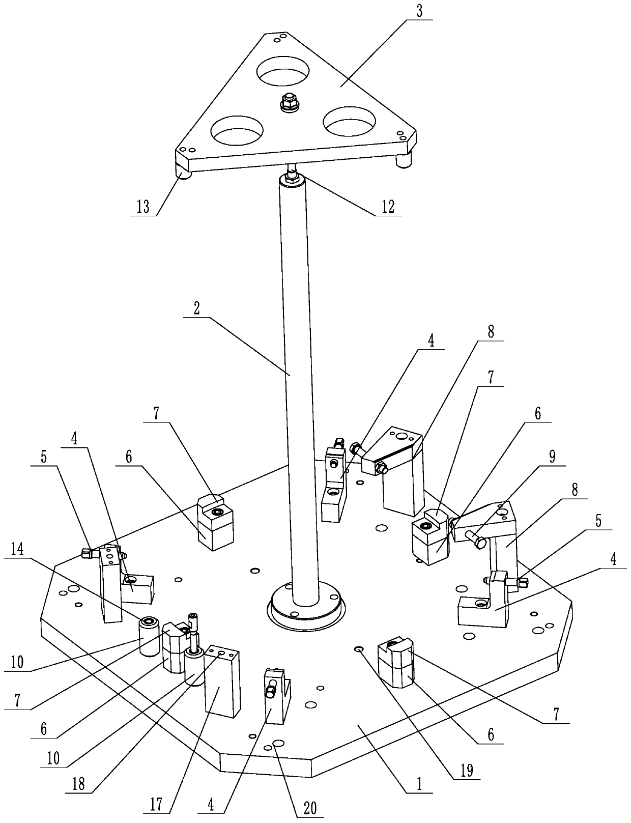
[0029] Example 2: A universal cylindrical workpiece processing tool (see attached image 3 , attached Figure 4), its structure is similar to that of Embodiment 1, the main difference is that in this embodiment, the pressure plate has a Y-shaped structure, three pressure arms 21 are evenly distributed on the pressure plate, and a pressure plate support foot is installed at the end of the pressure arm. The lower part of the upper pressing plate of the locking rod is sleeved with a template 22 which is adapted to the upper end of the cylindrical workpiece. The template is provided with a positioning through hole 23 corresponding to the supporting foot of the pressing plate. positioned in the through hole. The other structures are the same as those of Embodiment 1.

[0030] When the cylinder workpiece is processed with or without vertical lathe, the support block is removed from the positioning support seat, the lower end of the cylinder workpiece is supported on the support sc...

Embodiment 3

[0031] Example 3: A universal cylindrical workpiece processing tool (see attached Figure 5 , attached Image 6 ), its structure is similar to Embodiment 1, the main difference is that in this embodiment, three radially arranged chute 24 are evenly arranged on the pressure plate, an annular groove 25 is arranged in the middle of the pressure plate, the chute and the annular groove pass through, and the bottom surface of the annular groove The middle position is provided with a stud 26, the stud is connected with a threaded sleeve 27, and the outer wall of the threaded sleeve is provided with a push block 28 in one-to-one correspondence with the chute, and the distance between the outer wall of the push block and the axis of the stud is clockwise or counterclockwise. The direction gradually increases, a self-centering rod 29 is installed in the chute, one end of the self-centering rod extends out of the chute and abuts on the outer wall of the screw sleeve, and a positioning sp...


PUM


Abstract

The invention discloses a universal type cylindrical workpiece machining, and aims to overcome the defects that a cylindrical workpiece machining tooling is poor in generality and is only suitable fora machining process for one type of workpieces, and the cost is increased. The universal type cylindrical workpiece machining tooling comprises a base, a positioning post and a pressing plate; the lower end of the positioning post is connected to the base; a side ejection block is mounted at each corner position of the base; each side ejection block is connected with a threaded ejection rod whichis arranged in a manner of facing the positioning post in the radial direction; a positioning supporting seat is mounted between adjacent two side ejection blocks; a supporting block is detachably mounted on the positioning supporting seat; positioning ejection blocks are mounted on the two sides of the positioning supporting seat on one side of the base; each positioning ejection block is in threaded connection with a positioning ejection rod; supporting seats are mounted on the two sides of the positioning supporting seat on the other opposite side of the base; a plurality of supporting screw rods are uniformly distributed and mounted on the base; the upper end of the positioning post is detachably connected with a locking piece; the pressing plate is mounted on the locking rod in a sleeving manner; a plurality of pressing plate supporting feet are uniformly distributed and connected on the pressing plate; and the upper end of the locking rod is connected with a locking mechanism which is used for locking the pressing plate.

Description

technical field [0001] The present invention relates to a tooling, more particularly, it relates to a universal cylindrical workpiece processing tooling. Background technique [0002] At present, there are various types of cylindrical workpieces in the new products developed by our company. These parts have different shapes and lengths, and require different processing techniques and process equipment during processing. If each part is designed with a process and tooling, it has high management and cost requirements for the company. If the parts can have a flexible process and a common tooling, then some practical management and operation problems can be solved and production costs can also be saved. For example, the process design of this product can be divided into a vertical lathe process and a non-vertical lathe process. Each process has its own characteristics. The vertical lathe process will improve the processing efficiency, and the non-vertical lathe process is char...

Claims


Application Information

Patent Timeline
IPC IPC(8): B23Q3/06
Inventor 孙袁李金凑马春元施思
Owner 杭州联德精密机械股份有限公司
Features
  • R&D
  • Intellectual Property
  • Life Sciences
  • Materials
  • Tech Scout
  • Unparalleled Data Quality
  • Higher Quality Content
  • 60% Fewer Hallucinations
Learn More