Storage battery assembly and automobile
A battery and component technology, which is applied to vehicle components, circuits or fluid pipelines, transportation and packaging, etc., can solve the problems of small space in the engine compartment, increase of batteries, battery leakage, etc., and achieve simple installation and operation, improved stability, space-saving effect
- Summary
- Abstract
- Description
- Claims
- Application Information
AI Technical Summary
Problems solved by technology
Method used
Image
Examples
Embodiment 1
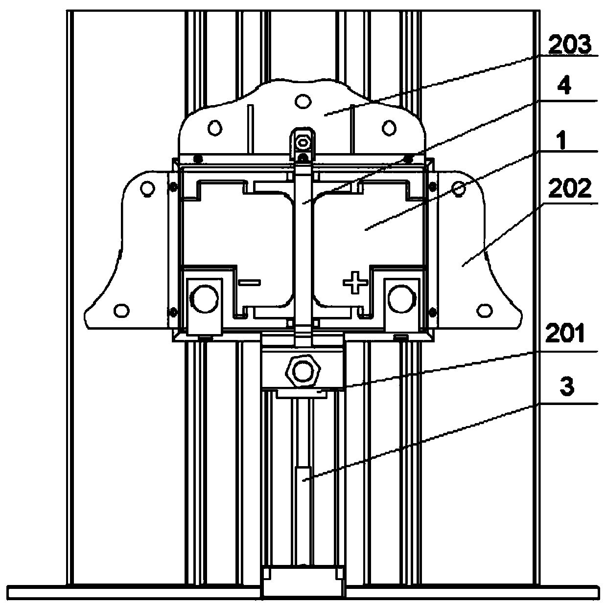
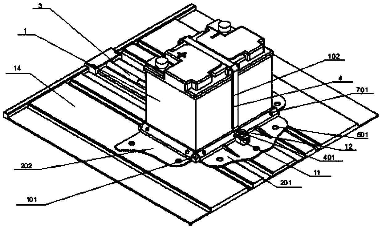
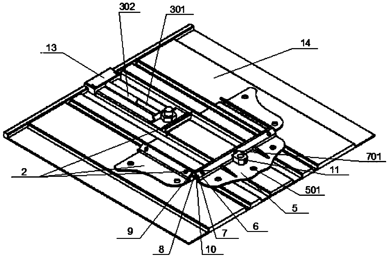
[0033] Such as Figure 1 to Figure 3 Shown: a battery assembly, including a battery 1, a battery chassis support 2, a mechanical pressure bar 3 and a fixing belt 4;
[0034] The battery chassis support 2 includes a first support 201, a second support 202 and a third support 203, and the first support 201, the second support 202 and the third support 203 are all used to fix the battery 1;
[0035] The mechanical pressure rod 3 is fixedly connected to the end of the first bracket 201 away from the battery 1 , and the mechanical pressure rod 3 is used to push the first bracket 201 along the connection direction between the first bracket 201 and the battery 1 exercise;
[0036] One end of the fixing belt 4 is fixedly connected to the first bracket 201, and the other end is detachably connected to the third bracket 203;
[0037] The side wall of the storage battery 1 is provided with a wall groove 102 matched with the fixing belt 4, and the wall groove 102 is used to accommodate...
Embodiment 2
[0042] Embodiment 2: be the preferred embodiment of embodiment 1
[0043] Such as Figure 1 to Figure 3 Shown: a battery assembly, including battery 1, battery chassis support 2, mechanical pressure bar 3 and fixing belt 4;
[0044] The battery chassis support 2 includes a first support 201, a second support 202 and a third support 203, and the first support 201, the second support 202 and the third support 203 are all used to fix the battery 1;
[0045] The mechanical pressure rod 3 is fixedly connected to the end of the first bracket 201 away from the battery 1 , and the mechanical pressure rod 3 is used to push the first bracket 201 along the connection direction between the first bracket 201 and the battery 1 exercise;
[0046] One end of the fixing belt 4 is fixedly connected to the first bracket 201, and the other end is detachably connected to the third bracket 203;
[0047] The side wall of the storage battery 1 is provided with a wall groove 102 matched with the f...
Embodiment 3
[0063] Embodiment 3: be the preferred embodiment of embodiment 2
[0064] The difference with embodiment 2 is:
[0065] The third bracket 203 is further provided with at least one reinforcing rib, which can strengthen the rigidity of the third bracket 203 and securely fasten the fixing belt on the connecting block 11 .
[0066] Such as figure 2 As shown, there are two transition blocks on the top of the battery 1 away from the battery base 101, and the transition blocks are respectively provided with notches that engage with the fixing belt 4, which can strengthen the fixing belt 4 and the upper wall groove 102 on the side wall of the battery 1. closeness of contact.
[0067] Further preferably, the fixing belt 4 is a belt.
PUM
 Abstract
Description
Claims
Application Information
 - R&D
- Intellectual Property
- Life Sciences
- Materials
- Tech Scout
- Unparalleled Data Quality
- Higher Quality Content
- 60% Fewer Hallucinations
Browse by: Latest US Patents, China's latest patents, Technical Efficacy Thesaurus, Application Domain, Technology Topic, Popular Technical Reports.
© 2025 PatSnap. All rights reserved.Legal|Privacy policy|Modern Slavery Act Transparency Statement|Sitemap|About US| Contact US: help@patsnap.com


