Chemical dosing equipment for flocculating tank

A technology of dosing equipment and flocculation tank, applied in the direction of flocculation/sedimentation water/sewage treatment, etc., can solve the problems of high labor intensity of manual stirring and uneven delivery of coagulant, and achieve easy contact, fast response, and uniform stirring. Effect

Inactive Publication Date: 2019-05-28
刘君保
View PDF5 Cites 5 Cited by
  • Summary
  • Abstract
  • Description
  • Claims
  • Application Information

AI Technical Summary

Problems solved by technology

[0003] In order to overcome the disadvantages of uneven delivery of coagulant and high labor intensity of manual stirring when people add coagulant to the flocculation tank, the purpose of this invention is to provide a flocculation tank dosing equipment that is more uniform and reduces labor intensity.

Method used


Image

  • Chemical dosing equipment for flocculating tank
  • Chemical dosing equipment for flocculating tank
  • Chemical dosing equipment for flocculating tank

Examples


Embodiment 1

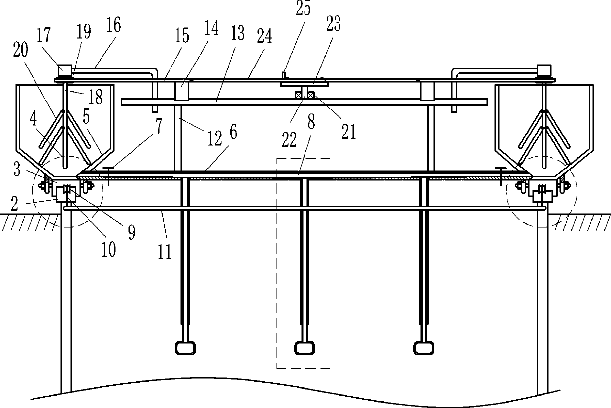
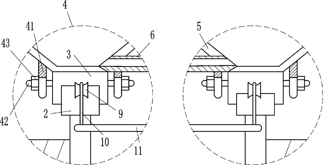
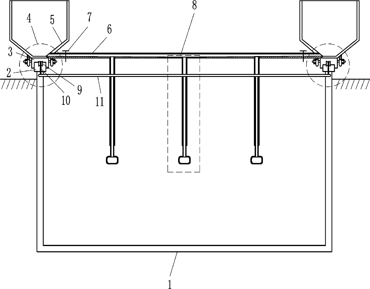
[0023] A flocculation tank dosing equipment, such as Figure 1-5 As shown, it includes a guide rail 2, a guide block 3, a fixing device 4, a storage hopper 5, a pipeline 6, a valve 7 and a feeding device 8, and the left and right sides of the top of the flocculation tank body 1 are provided with a guide rail 2, and the slide type on the guide rail 2 A guide block 3 is provided, the left and right sides of the guide block 3 are provided with fixing devices 4, the top of the fixing devices 4 on the left and right sides of the guide block 3 is provided with a storage hopper 5, and a pipeline 6 is arranged between the left and right storage hoppers 5, and the pipeline 6. There are valves 7 on the left and right sides. Three feeding devices 8 are evenly arranged at the bottom of the pipeline 6. The feeding devices 8 are located between the left and right valves 7. The lower part of the feeding device 8 is located in the flocculation tank body 1.

Embodiment 2

[0025] A flocculation tank dosing equipment, such as Figure 1-5 As shown, it includes a guide rail 2, a guide block 3, a fixing device 4, a storage hopper 5, a pipeline 6, a valve 7 and a feeding device 8, and the left and right sides of the top of the flocculation tank body 1 are provided with a guide rail 2, and the slide type on the guide rail 2 A guide block 3 is provided, the left and right sides of the guide block 3 are provided with fixing devices 4, the top of the fixing devices 4 on the left and right sides of the guide block 3 is provided with a storage hopper 5, and a pipeline 6 is arranged between the left and right storage hoppers 5, and the pipeline 6. There are valves 7 on the left and right sides. Three feeding devices 8 are evenly arranged at the bottom of the pipeline 6. The feeding devices 8 are located between the left and right valves 7. The lower part of the feeding device 8 is located in the flocculation tank body 1.

[0026] Fixing device 4 comprises c...

Embodiment 3

[0028] A flocculation tank dosing equipment, such as Figure 1-5 As shown, it includes a guide rail 2, a guide block 3, a fixing device 4, a storage hopper 5, a pipeline 6, a valve 7 and a feeding device 8, and the left and right sides of the top of the flocculation tank body 1 are provided with a guide rail 2, and the slide type on the guide rail 2 A guide block 3 is provided, the left and right sides of the guide block 3 are provided with fixing devices 4, the top of the fixing devices 4 on the left and right sides of the guide block 3 is provided with a storage hopper 5, and a pipeline 6 is arranged between the left and right storage hoppers 5, and the pipeline 6. There are valves 7 on the left and right sides. Three feeding devices 8 are evenly arranged at the bottom of the pipeline 6. The feeding devices 8 are located between the left and right valves 7. The lower part of the feeding device 8 is located in the flocculation tank body 1.

[0029]Fixing device 4 comprises co...


PUM


Abstract

The invention relates to chemical dosing equipment and in particular relates to chemical dosing equipment for a flocculating tank. The invention aims at providing the chemical dosing equipment for theflocculating tank, which can be used for more uniformly dosing chemicals and reducing the labor intensity of people. According to the technical scheme provided by the invention, the chemical dosing equipment for the flocculating tank comprises guide rails and the like; the guide rails are arranged at left and right sides of the top of a flocculating tank body; guide blocks are arranged on the guide rails in a sliding manner; fixing devices are arranged at the left and right sides of the guide blocks; storage hoppers are arranged at the tops of the fixing devices at the left and right sides ofthe guide blocks; a pipeline is arranged between the storage hoppers at the left and right sides; valves are arranged at the left and right sides of the pipeline; three discharging devices are uniformly arranged at the bottom of the pipeline. According to the chemical dosing equipment for the flocculating tank, the discharging devices are arranged; when people need to add a coagulant, the valvesare opened and a coagulant solution flows into the discharging devices through the pipeline and then is discharged into the flocculating tank body; meanwhile, people push the storage hoppers to move frontward and backward, so that the coagulant solution and sewage are uniformly stirred and the flocculating effect is improved.

Description

technical field [0001] The invention relates to a dosing device, in particular to a dosing device for a flocculation tank. Background technique [0002] In sewage treatment, in order to improve the flocculation effect of the flocculation tank, it is often necessary to add some auxiliary agents such as flocculants and coagulants to the flocculation tank to improve the flocculation effect. At present, people usually add coagulants to the flocculation tank manually. The coagulant is placed in the pool, the manual input is not uniform enough, the flocculation effect is not good enough, and the flocculation efficiency is low; and after the injection, in order to improve the effect, people need to hold sticks to stir the sewage in the flocculation pool, so people's The labor intensity is high, people's labor will be heavy, and people will feel very tired. Contents of the invention [0003] In order to overcome the shortcomings of uneven coagulant injection and labor-intensive m...

Claims


Application Information

Patent Timeline
Patent Type & Authority Applications(China)
IPC IPC(8): C02F1/52
Inventor 刘君保
Owner 刘君保
Why Eureka
Try Eureka