Oil filter capable of preventing oil leakage during dismounting and mounting
An oil filter and oil leakage prevention technology, which is applied in the field of filters, can solve problems such as oil leakage, and achieve the effects of easy installation, flexible and convenient installation, and easy disassembly
- Summary
- Abstract
- Description
- Claims
- Application Information
AI Technical Summary
Problems solved by technology
Method used
Image

Examples
Embodiment 1
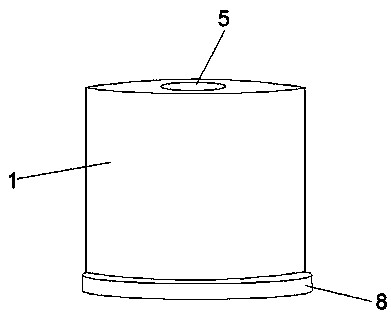
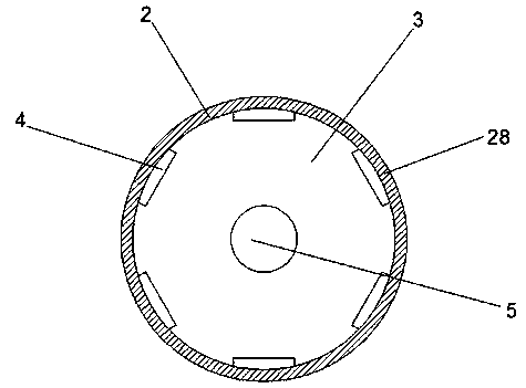
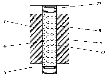
[0027] see Figure 1-5 , according to an embodiment of the present invention, an oil filter for disassembling and installing oil leakage prevention includes a housing 1, a sealing groove 2 at the top of the housing 1, a sealing ring 28 is arranged in the sealing groove 2, and the One side of the sealing groove 2 is provided with a metal splint 3, and several dirty oil inlets 4 are arranged between the sealing groove 2 and the metal splint 3, and a clean oil outlet 5 is provided in the middle of the metal splint 3, and the clean oil outlet 5 A central pipe 6 is provided inside, and a filter paper 7 is provided on the outside of the central pipe 6, a check valve 9 is provided at the bottom of the filter paper 7, a mounting part 8 is provided at the bottom of the housing 1, and a symmetrical design is arranged inside the mounting part 8. There is a cavity 10, a worm wheel 11 is arranged in the cavity 10, the middle part of the worm wheel 11 is connected with the cavity 10 through...
Embodiment 2
[0030] see image 3 and Figure 4 , for the clean oil outlet 5, both ends of the clean oil outlet 5 are provided with internal threads 27. As for the central pipe 6 , several filter element through holes 20 are provided on the central pipe 6 . For the mounting part 8 , a connecting pipe 21 is provided in the middle of the mounting part 8 , and an external thread 26 is provided on the outside of one end of the connecting pipe 21 , and the connecting pipe 21 is matched with the clear oil outlet 5 .
[0031] Through the above scheme of the present invention, the beneficial effect is that internal threads are provided at both ends of the clean oil outlet 5, and a connecting pipe 21 is provided in the middle of the mounting part 8, and an external thread is provided on the outside of the connecting pipe 21, thereby facilitating installation. The effect of the oil filter and the mounting part 8 is convenient for dismounting.
Embodiment 3
[0033] see Figure 5 , for the cavity 10 , a baffle 22 is provided in the cavity 10 , and the baffle 22 is located on one side of the worm wheel 11 . For the cavity 10 , a fixed ring 23 is provided in the cavity 10 , and the end of the worm 15 away from the male gear 16 penetrates through the fixed ring 23 and extends into the fixed ring 23 . As for the rotating shaft 18 , the rotating shaft 18 is covered with a fixed sleeve 24 , and the fixed sleeve 24 is connected to the inner wall of the cavity 10 through a connecting rod 25 .
[0034] Through the above solution of the present invention, the beneficial effect is that by providing the baffle plate 22 in the cavity 10 , oil leakage from the cavity 10 is avoided. By providing the fixing ring 23 and the fixing sleeve 24 , the worm screw 15 and the rotating shaft 18 can be used as position-limiting supports.
[0035]In summary, with the help of the above-mentioned technical solution of the present invention, the working princi...
PUM
 Abstract
Description
Claims
Application Information
 - R&D
- Intellectual Property
- Life Sciences
- Materials
- Tech Scout
- Unparalleled Data Quality
- Higher Quality Content
- 60% Fewer Hallucinations
Browse by: Latest US Patents, China's latest patents, Technical Efficacy Thesaurus, Application Domain, Technology Topic, Popular Technical Reports.
© 2025 PatSnap. All rights reserved.Legal|Privacy policy|Modern Slavery Act Transparency Statement|Sitemap|About US| Contact US: help@patsnap.com