Micro-vibration energy-consumption viscoelastic buckling restrained brace

A buckling constraint and viscoelastic technology, applied in building components, shockproof and other directions, can solve problems such as inability to consume energy, and achieve the effect of simple installation, simple production, convenient and flexible installation

Active Publication Date: 2013-07-17
SOUTHEAST UNIV
View PDF13 Cites 7 Cited by
  • Summary
  • Abstract
  • Description
  • Claims
  • Application Information

AI Technical Summary

Problems solved by technology

[0005] In order to solve the problem that the traditional buckling-constrained support can only act as a common support and cannot consume energy under the action of small earthquakes or wind vibrations, the present invention provides a micro-vibration energy-dissipating viscoelastic buckling-constrained support

Method used


Image

  • Micro-vibration energy-consumption viscoelastic buckling restrained brace
  • Micro-vibration energy-consumption viscoelastic buckling restrained brace
  • Micro-vibration energy-consumption viscoelastic buckling restrained brace

Examples


Embodiment 1

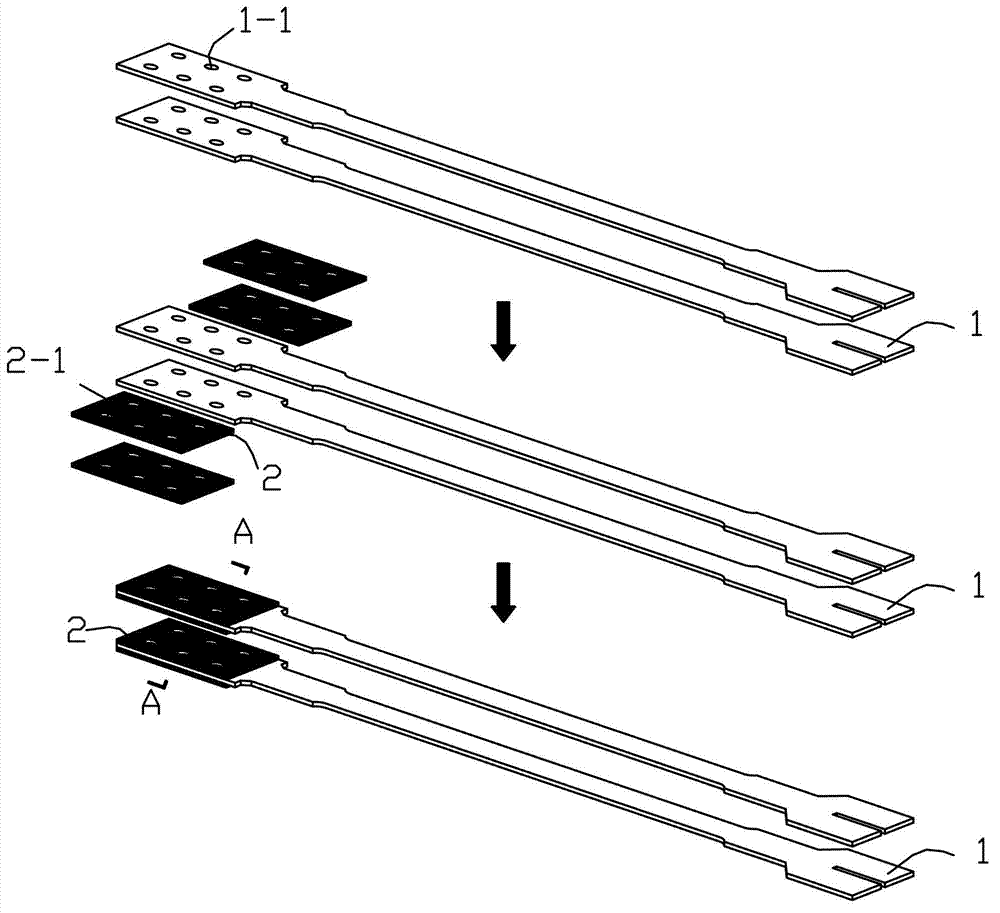
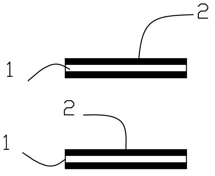
[0028] Embodiment one: if Figure 1~9 As shown, the micro-vibration dissipative energy-dissipating viscoelastic buckling constrained support of this embodiment is composed of two energy-dissipating inner core plates 1, a viscoelastic material body 2, a buckling constraining component 3, and a restraining force-transmitting component 4. One end of the core plate 1 is provided with several first deformation holes 1-1, wherein the deformation holes 1-1 can be oval holes, oblong holes, waist-shaped holes or elongated holes, etc., in this embodiment, the first The deformation hole 1-1 is an elliptical hole, and the end of the energy-dissipating inner core plate 1 with the elliptical hole is located in the restraining force transmission part 4, and the middle section of the energy-dissipating inner core plate 1 is located in the buckling restraining part 3, and the energy-dissipating inner core plate The other end of 1 protrudes outside the buckling constraining part 3, and the visc...

Embodiment 2

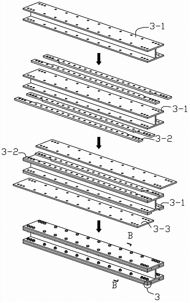
[0029] Embodiment two: if image 3 As shown, the shape of each first filling plate 3-2 in this embodiment corresponds to the side shape of each energy-dissipating inner core plate 1, and each filling plate 3-2 is located on the first I-shaped steel plate 3-1. And in the middle of the two first cover plates 3-3, every two first filling plates 3-2 are located on the upper and lower surfaces of the first I-shaped steel 3-1, and the outside of every two first filling plates 3-2 is a The gap between the first cover plate 3-3, the first filling plate 3-2 and the first cover plate 3-3 and the energy dissipation inner core plate 1 is about 1-2mm, and the in-plane and Out-of-plane buckling. Other compositions and connection methods are the same as those in Embodiment 1.

Embodiment 3

[0030] Embodiment three: as Figure 5 As shown, each filling plate 4-2 of this embodiment is located in the middle of the second I-shaped steel 4-1 and the two second cover plates 4-3, and every two second filling plates 4-2 are located in the middle of the second I-shaped steel plate 4-1. The upper and lower surfaces of the glyph steel 4-1, the outside of every two second filling plates 4-2 is a second cover plate 4-3, the second filling plate 4-2, the second cover plate 4-3 and the second working plate The space formed by the font-shaped steel 4-1 is 1-2mm wider than the viscoelastic material body 2, which plays a role in protecting the viscoelastic material body 2. Other compositions and connection methods are the same as those in Embodiment 2.


PUM


Abstract

The invention discloses a micro-vibration energy-consumption viscoelastic buckling restrained brace. The micro-vibration energy-consumption viscoelastic buckling restrained brace comprises energy-consumption inner core plates, viscoelastic material bodies, buckling restrained parts and restrained force transmission parts, wherein one ends of the energy-consumption inner core plates are arranged in the restrained force transmission parts; the middle sections of the energy-consumption inner core plates are arranged in the buckling restrained parts, and a gap of 1mm-2mm exists between the middle section of each energy-consumption inner core plate and the corresponding buckling restrained part; the other ends of the energy-consumption inner core plates extend out of the buckling restrained parts; the upper and lower surfaces of each energy-consumption inner core plate, at one end of the corresponding restrained force transmission part, are fixedly and respectively connected with a viscoelastic material body; and the viscoelastic material bodies are fixedly connected with the inner surfaces of the restrained force transmission parts. The brace can consume energy under the action of small seisms or wind vibration and dissipate energy of an earthquake under the action of a middle or large earthquake and also supplies certain bracing rigidity to a structure, thus expanding the application of the buckling restrained brace to a wind sensitive structure.

Description

technical field [0001] The invention belongs to the field of civil engineering and relates to a buckling constraint support for reducing the seismic response of engineering structures. Background technique [0002] Buckling-constrained support is a new type of support with dual functions of ordinary support and metal damper. Under the action of small earthquake or wind vibration, the energy-dissipating inner core plate is in the elastic range, and the buckling-constrained support is equivalent to a central support that does not lose stability. , to provide lateral stiffness to the main structure; under the action of moderate or large earthquakes, the buckling restraint supports dissipate the vibration energy through the tensile and compressive yielding of the energy-dissipating inner core plate. However, for structures that are wind-sensitive and need to consider shock absorption, traditional buckling-restrained braces can only act as ordinary central braces and cannot dissi...

Claims


Application Information

Patent Timeline
Patent Type & Authority Applications(China)
IPC IPC(8): E04B1/98
Inventor 王春林曾鹏葛汉彬曾滨吴京
Owner SOUTHEAST UNIV
Why Eureka
Try Eureka