
A high-rigidity electric lift insulation cabin

An electric and electric technology of rigidity, applied in the field of high-stiffness electric lifting and insulation cabins, can solve the problems of self-locking stability safety hazards of the lifting mechanism, limitations of the lifting mechanism, etc., and achieve strong designability, good sealing, and thermal insulation performance excellent effect

Active Publication Date: 2021-08-06
CHINA JIUYUAN HI TECH EQUIP
View PDF6 Cites 0 Cited by
  • Summary
  • Abstract
  • Description
  • Claims
  • Application Information

AI Technical Summary

Problems solved by technology

[0004] The purpose of the present invention is to provide a high-rigidity electric lifting insulation cabin, which is used to solve the problem that the lifting mechanism has great limitations when some components and structures in the lifting equipment in the prior art need to work in a heat preservation environment. At the same time, the self-locking stability of the existing lifting mechanism during work is also a potential safety hazard.

Method used


Image

  • A high-rigidity electric lift insulation cabin
  • A high-rigidity electric lift insulation cabin

Examples


Embodiment 1

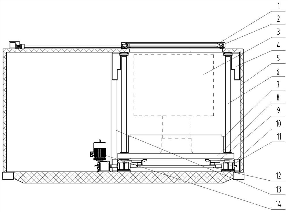
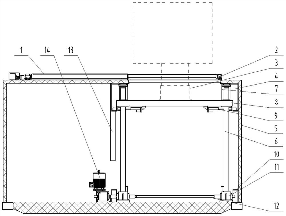
[0027] combined with figure 1 and 2As shown, a high-rigidity electric lifting insulation cabin includes a shelter 5 and a motor 14 arranged in the shelter 5. The top surface of the shelter 5 is provided with an opening, and the edge of the opening is provided with a top frame plate 2, and the top frame plate 2 is provided with an electric top cover 1; the shelter 5 is provided with 4 lead screw pairs 6 fixedly connected with the shelter 5 through a fixing device, the lower end of the lead screw pair 6 is provided with a commutator 11, and the upper end of the lead screw pair 6 A platform 8 is provided in common, on which a thermal insulation compartment 7 is provided, and an electric locking mechanism 9 is provided on the underside of the platform 8; Respectively matched with the commutator 11, the purpose of the present invention is to provide a high-rigidity electric lifting insulation cabin for the deficiencies in the existing shelter 5 lifting mechanism technology, which ...


PUM


Abstract

The invention discloses a high-rigidity electric lifting insulation cabin, which relates to the technical field of insulation cabins, and includes a shelter and a motor arranged in the shelter. There is an electric top cover on the frame plate; there are at least 4 lead screw pairs fixedly connected to the shelter through the fixing device in the shelter, the lower end of the lead screw pair is provided with a commutator, and a platform is set on the lead screw pair , the platform is provided with a thermal insulation compartment, and the lower side of the platform is provided with an electric locking mechanism; the motor is connected to the worm gear reducer and the connecting shaft in turn, and the two ends of the connecting shaft are matched with the commutator respectively. The purpose of the present invention is to Aiming at the deficiencies in the existing shelter lifting mechanism technology, a high-rigidity electric lifting insulation cabin is provided. This solution combines the screw drive form of the existing shelter lifting mechanism technology, and is changed to use at least 4 T-shaped The lead screw pair is used as a transmission element to increase the self-locking stability and synchronization of the lifting structure during work.

Description

technical field [0001] The invention relates to the technical field of insulation cabin equipment, in particular to a high-rigidity electric lifting insulation cabin. Background technique [0002] With the continuous development of science and technology, square cabins are more and more widely used in military equipment and civilian equipment. For radar antennas, photoelectric equipment, turrets and other application equipment, more and more cabin equipment requires automatic opening during work. The cabin roof is automatically and stably and quickly lifted out of the cabin for work. After the work is completed, it is automatically and stably and quickly lowered back into the cabin, and the cabin roof is automatically closed for transportation. The transmission unit composed of worm gear reducer and screw pair has been widely used in various industries. Especially for large and heavy equipment in the cabin, the lifting mechanism composed of worm gear reducer and screw pair ...

Claims


Application Information

Patent Timeline
Patent Type & Authority Patents(China)
IPC IPC(8): F16M11/24F16M11/04F16M11/18F16L59/00
Inventor 吴春霞刘晨星王楚高宇林
Owner CHINA JIUYUAN HI TECH EQUIP
Learn More