

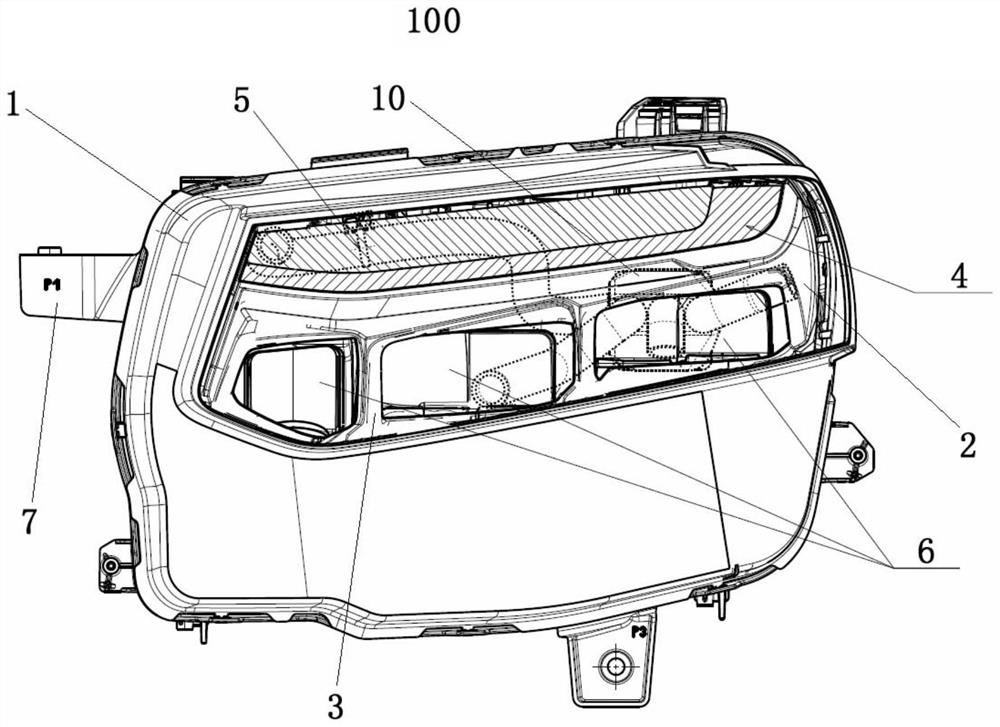
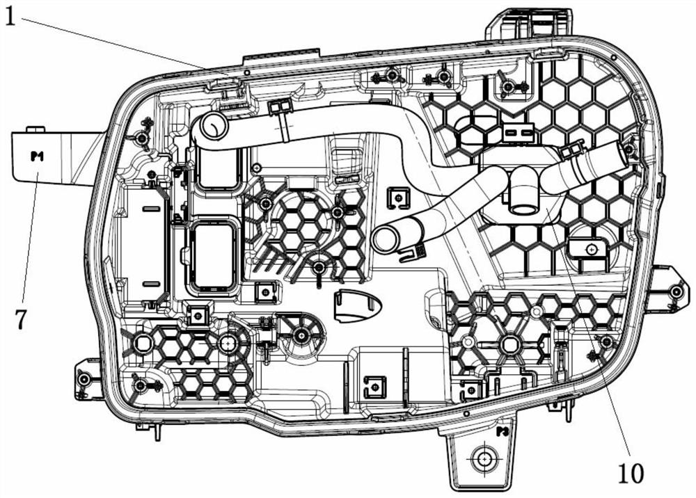
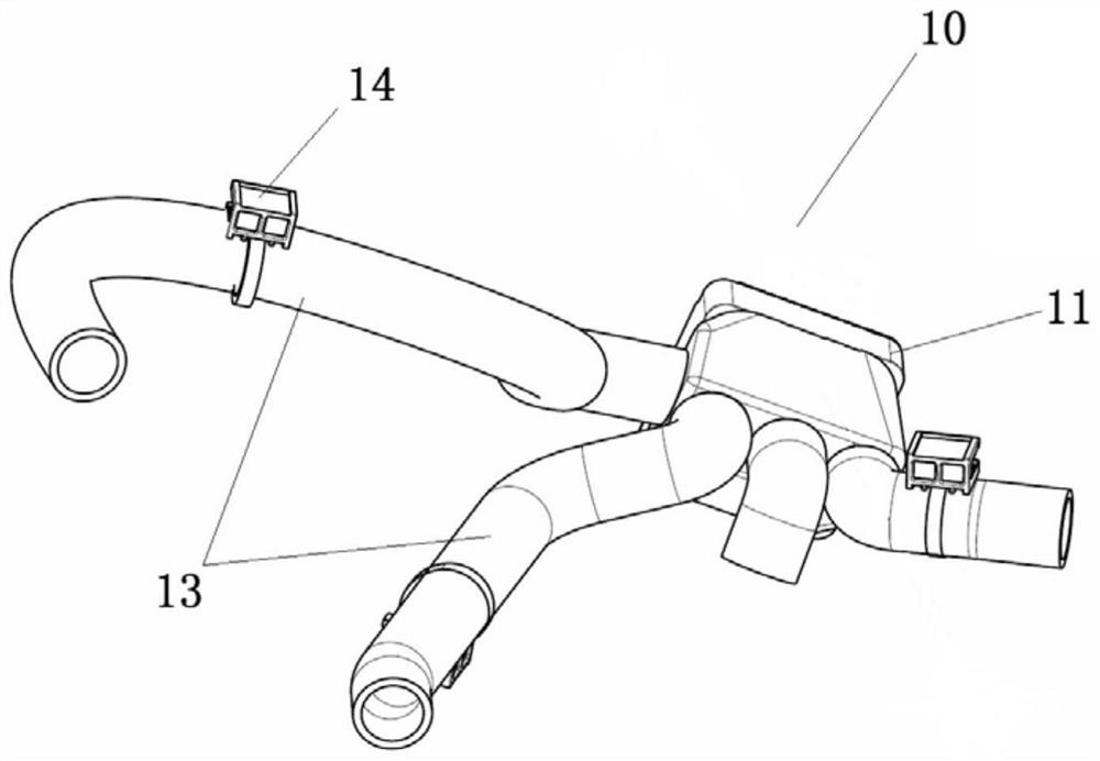
Lighting device for motor vehicles and vehicle
A light-emitting device and motor vehicle technology, applied in the field of vehicles and motor vehicles, can solve the problems of low cost, water accumulation in car lights, diminishing efficacy, etc., and achieve the effects of simple installation and fixing, demisting function, and increased air flow
- Summary
- Abstract
- Description
- Claims
- Application Information
AI Technical Summary
Problems solved by technology
Method used
Image

Examples
Embodiment Construction
[0024] Exemplary embodiments of the present invention will be described in detail below with reference to the accompanying drawings, wherein the same reference numerals represent the same or similar elements. In addition, in the following detailed description, for purposes of explanation, numerous specific details are set forth in order to provide a comprehensive understanding of the embodiments of the present disclosure. It may be evident, however, that one or more embodiments may be practiced without these specific details. In other instances, well-known structures and devices are shown in diagrammatic form to simplify the drawings.
[0025] The embodiments of the present invention illustrate the defogging principle of the light emitting device by taking the LED light source as an example of the light source of the light emitting device of a motor vehicle. In the lighting device of motor vehicles, the LED light source (especially the full LED light source) generates less he...
PUM
 Abstract
Description
Claims
Application Information