
An air-cooling and water-cooling hybrid heat dissipation case

A hybrid, cold water technology, applied in the direction of instruments, electrical digital data processing, digital data processing components, etc., can solve the problem of unreasonable installation position and air flow setting of air cooling device and water cooling device, chassis shock absorption and noise reduction Poor, unable to further enhance the heat dissipation effect, etc., to achieve the effect of increasing the heat dissipation effect, good shock and noise reduction effects, and a simple structure

Inactive Publication Date: 2019-05-28
HUNAN UNIV OF ARTS & SCI
View PDF4 Cites 4 Cited by
  • Summary
  • Abstract
  • Description
  • Claims
  • Application Information

AI Technical Summary

Problems solved by technology

[0004] The purpose of the present invention is to provide an air-cooled and water-cooled hybrid heat dissipation chassis to solve the problem that the water-cooled device and the air-cooled device proposed in the background technology can only be installed separately and cannot be installed in coordination. The settings are not reasonable enough, so that they cannot cooperate with each other, and the heat dissipation effect cannot be further enhanced; the shock absorption and noise reduction effects of the chassis are poor, and the chassis is prone to noise and vibration during operation; the water cooling device has a complex structure, poor cooling effect, and occupies a large volume Large, inconvenient installation and removal problems

Method used


Image

  • An air-cooling and water-cooling hybrid heat dissipation case
  • An air-cooling and water-cooling hybrid heat dissipation case
  • An air-cooling and water-cooling hybrid heat dissipation case

Examples


Embodiment Construction

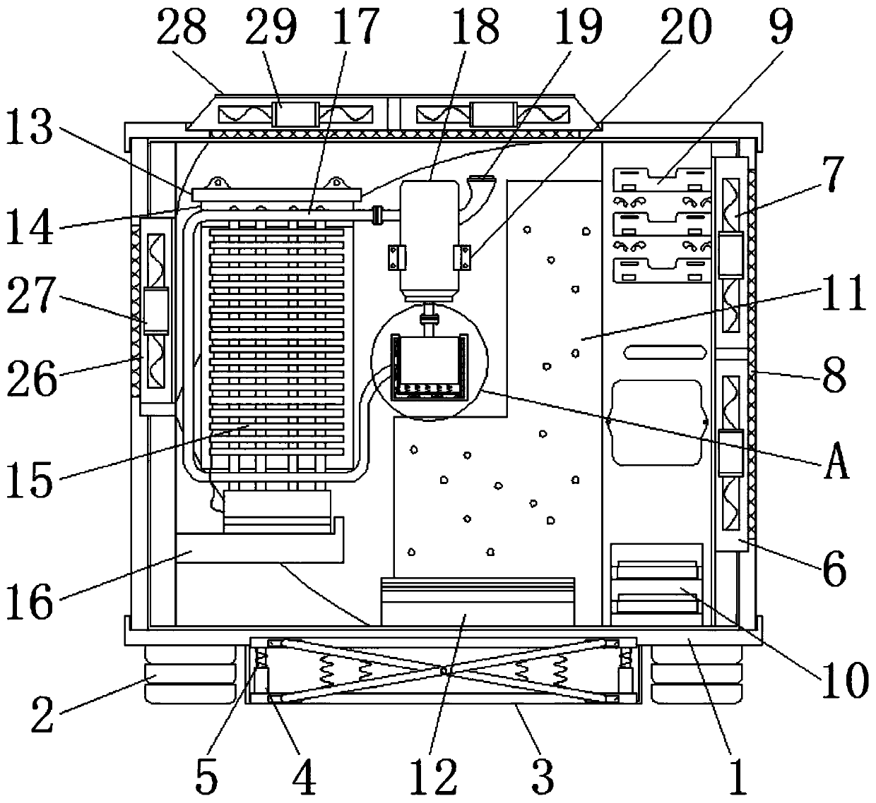
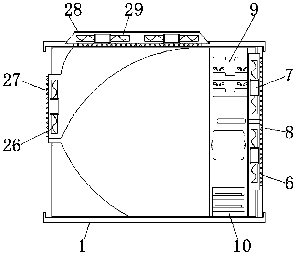
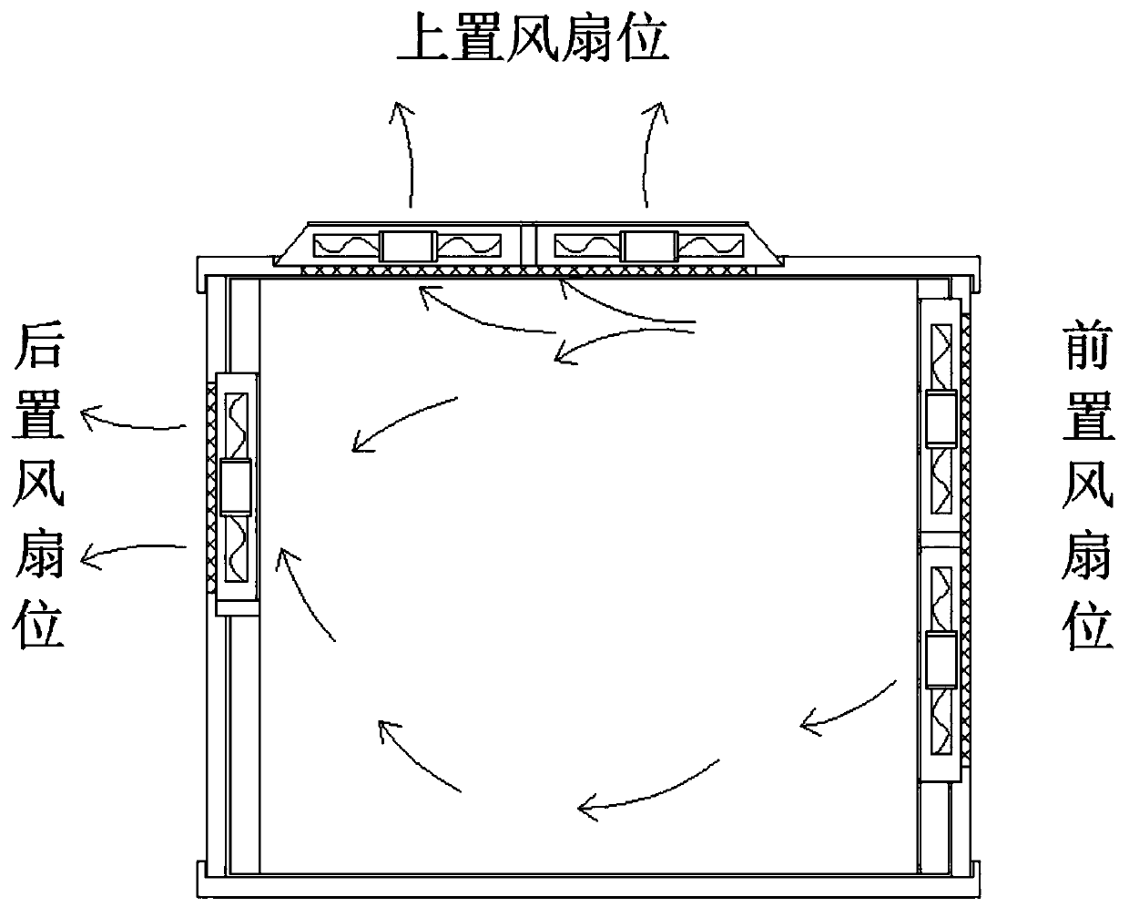
[0028] The following will clearly and completely describe the technical solutions in the embodiments of the present invention with reference to the accompanying drawings in the embodiments of the present invention. Obviously, the described embodiments are only some, not all, embodiments of the present invention. Based on the embodiments of the present invention, all other embodiments obtained by persons of ordinary skill in the art without making creative efforts belong to the protection scope of the present invention.

[0029] see Figure 1-7, the present invention provides a technical solution: an air-cooled and water-cooled hybrid heat dissipation chassis, including a box body 1, a pad 2, a buffer structure 3, a telescopic rod 4, a second spring 5, a front slot 6, a first fan 7. Ventilation plate 8, optical drive position 9, hard drive position 10, circuit board 11, power supply 12, first installation block 13, fixed plate 14, water cooling device 15, first support block 16...


PUM


Abstract

The invention discloses an air cooling and water cooling hybrid heat dissipation case. The case comprises a box body, a miniature booster pump and a sound insulation pad, cushion blocks are mounted onthe left side and the right side of the lower end surface of the box body, and telescopic rods are arranged on the inner sides of the left end and the right end of the buffer structure. A front groove position is reserved in the right side of the box body, and a CD-ROM drive position is arranged at the upper end of the right side in the box body. Circuit boards are tightly attached to the left sides of the CD-ROM position and the hard disk position, a first mounting block is mounted on the upper portion of the left side of the interior of the box body through bolts, a water cooling device istightly attached to the inner side of the fixing plate, a water pipe is tightly attached to the outer side of the upper end of the water cooling device, and a water adding port is mounted and connected to the right surface of the water storage tank. According to the air-cooling and water-cooling hybrid heat dissipation case, the water cooling device and the air cooling device are reasonably and effectively combined, so that the heat dissipation effect is further enhanced, the shock absorption and noise reduction effects are better, and the water cooling device is simple in structure and convenient to mount and dismount.

Description

technical field [0001] The invention relates to the technical field related to main chassis, in particular to an air-cooled and water-cooled hybrid cooling chassis. Background technique [0002] Insufficient heat dissipation capacity of the air-cooled radiator of the computer case will directly affect the fluency of computer operation and the service life of the chip. Therefore, a water-cooling system has been designed on the market, and the application is loaded into the computer. Experiments were carried out under different setting conditions to obtain the influence of air temperature, water temperature, chassis fan speed and pump power on its heat dissipation effect, thereby establishing the corresponding relationship between flow rate and thermal resistance, etc., so as to deploy the installation experiment of the water cooling device, water cooling Devices are greatly affected by water flow velocity, while fan speed has little effect on heat dissipation of various devic...

Claims


Application Information

Patent Timeline
Patent Type & Authority Applications(China)
IPC IPC(8): G06F1/20G06F1/18
Inventor 李剑波夏汉军庹雪峰彭进香刘治国谢雷铁席金菊
Owner HUNAN UNIV OF ARTS & SCI
Learn More