A three-dimensional blade modeling method for a multistage axial flow compressor based on an end region boundary layer and a blade

A technology for axial flow compressors and three-dimensional blades, which is applied to components, mechanical equipment, machines/engines, etc. of pumping devices for elastic fluids, and can solve the problem of increasing compressor design parameters without taking into account multi-stage axial flow compressors Improve the overall flow efficiency and surge margin, improve flow performance, and speed up the design process by solving problems such as flow characteristics and shape design parameters

Pending Publication Date: 2019-05-28
HANGZHOU TURBINE POWER GRP
View PDF2 Cites 3 Cited by
  • Summary
  • Abstract
  • Description
  • Claims
  • Application Information

AI Technical Summary

Problems solved by technology

[0004] The three-dimensional blade technology has the function of controlling the flow in the end area of ​​the diffuser cascade, but the three-dimensional blade increases the design parameters of the compressor, especially in the multi-stage axial flow compresso

Method used


Image

  • A three-dimensional blade modeling method for a multistage axial flow compressor based on an end region boundary layer and a blade
  • A three-dimensional blade modeling method for a multistage axial flow compressor based on an end region boundary layer and a blade
  • A three-dimensional blade modeling method for a multistage axial flow compressor based on an end region boundary layer and a blade

Examples


Example Embodiment

[0021] In order to make the objectives, technical solutions, and advantages of the embodiments of the present invention clearer, the technical solutions in the embodiments of the present invention will be described clearly and completely in conjunction with the accompanying drawings in the embodiments of the present invention. Obviously, the described embodiments It is a part of the embodiments of the present invention, but not all the embodiments. Based on the embodiments of the present invention, all other embodiments obtained by those of ordinary skill in the art without creative work shall fall within the protection scope of the present invention.

[0022] Hereinafter, the present invention will be further described through embodiments in combination with the drawings.

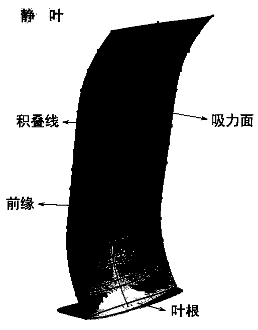
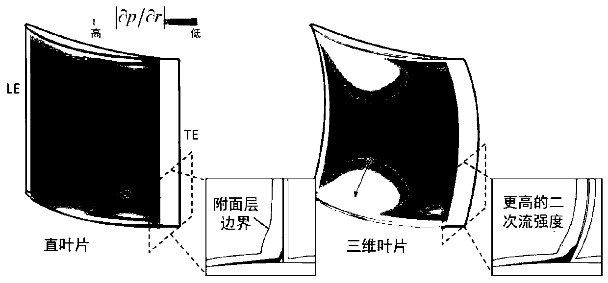
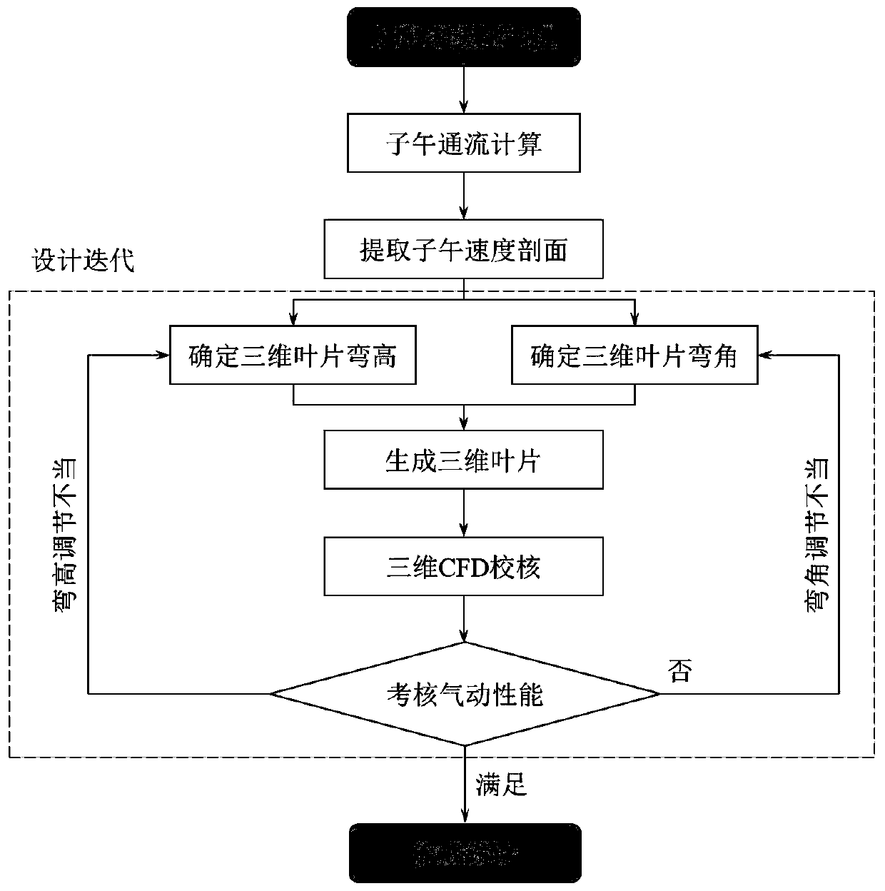
[0023] The invention is a three-dimensional blade modeling method of a multi-stage axial flow compressor based on the end zone attached surface layer. Based on the flow field characteristics of the multi-stage ...


PUM


Abstract

The invention relates to a three-dimensional blade modeling method for a multistage axial flow compressor based on an end region boundary layer. The three-dimensional blade modeling method is characterized by comprising the following steps of step 1, analyzing the meridian through-flow performance of the prototype multistage axial flow compressor; secondly, extracting the radial gradient of the meridian velocity profile through the through-flow performance in the first step, so that the boundary of a boundary layer is determined, and calculating the displacement thicknesses of the wheel flangeand the boundary layer of the wheel hub side; and step 3, determining initial three-dimensional blade modeling parameters, determining the bending height of the three-dimensional blade according to the relative blade height of the boundary of the corresponding side boundary layer, determining the bending angle of the three-dimensional blade according to the displacement thickness of the corresponding side boundary layer, and forming three-dimensional deformation of a stacking line according to the bending height and the bending angle to obtain the three-dimensional modeling of the blade. Theintegrated modeling design of the three-dimensional blade of the multistage axial flow compressor is realized, the multistage influence of the multistage axial flow compressor is considered, and the flow efficiency of the compressor is improved while the stable work of the compressor is ensured.

Description

technical field [0001] The invention relates to a three-dimensional modeling design method of a blade, in particular to a three-dimensional blade modeling method of a multistage axial flow compressor based on an end zone boundary layer. The invention belongs to the field of axial flow impeller machinery. Background technique [0002] The flow in the end zone of an axial compressor has always been one of the problems that limit the aerodynamic performance of the compressor. How to control the harsh end zone flow environment has become a technical bottleneck in the aerodynamic design of the compressor. In a multi-stage axial flow compressor, unlike single-row diffuser cascades or single-stage compressors, the flow states of each stage are not independent of each other, such as wake, separation and other flow phenomena will propagate to multiple cascade flow channels downstream, called It is the "multi-stage influence" of the multi-stage axial flow compressor. Due to its con...

Claims


Application Information

Patent Timeline
IPC IPC(8): G06F17/50F04D29/32
Inventor 丁骏辛小鹏隋永枫张伟杨晶晶但汉攀王宏泽冯俊玮郑健生
Owner HANGZHOU TURBINE POWER GRP
Why Eureka
Try Eureka