
A radio frequency payment module and a manufacturing method thereof

A technology of radio frequency payment and production method, which is applied in the field of smart cards, can solve the problems of strict structural requirements, the inability to mass-produce welding spot height changes, and unsuitable control of special-shaped products, so as to achieve the effect of not being able to mass-produce and solve diversification

Pending Publication Date: 2019-05-28
WATCHDATA SYST
View PDF0 Cites 0 Cited by
  • Summary
  • Abstract
  • Description
  • Claims
  • Application Information

AI Technical Summary

Problems solved by technology

The PCB board welding method cannot be mass-produced and the height of the solder joints changes with personnel changes. The structural requirements are relatively strict and special-shaped products are not suitable for control, which leads to the inability to promote large-scale special-shaped cards.

Method used


Image

  • A radio frequency payment module and a manufacturing method thereof
  • A radio frequency payment module and a manufacturing method thereof
  • A radio frequency payment module and a manufacturing method thereof

Examples


Embodiment Construction

[0032] The present invention will be further described in detail below in conjunction with the accompanying drawings and specific embodiments.

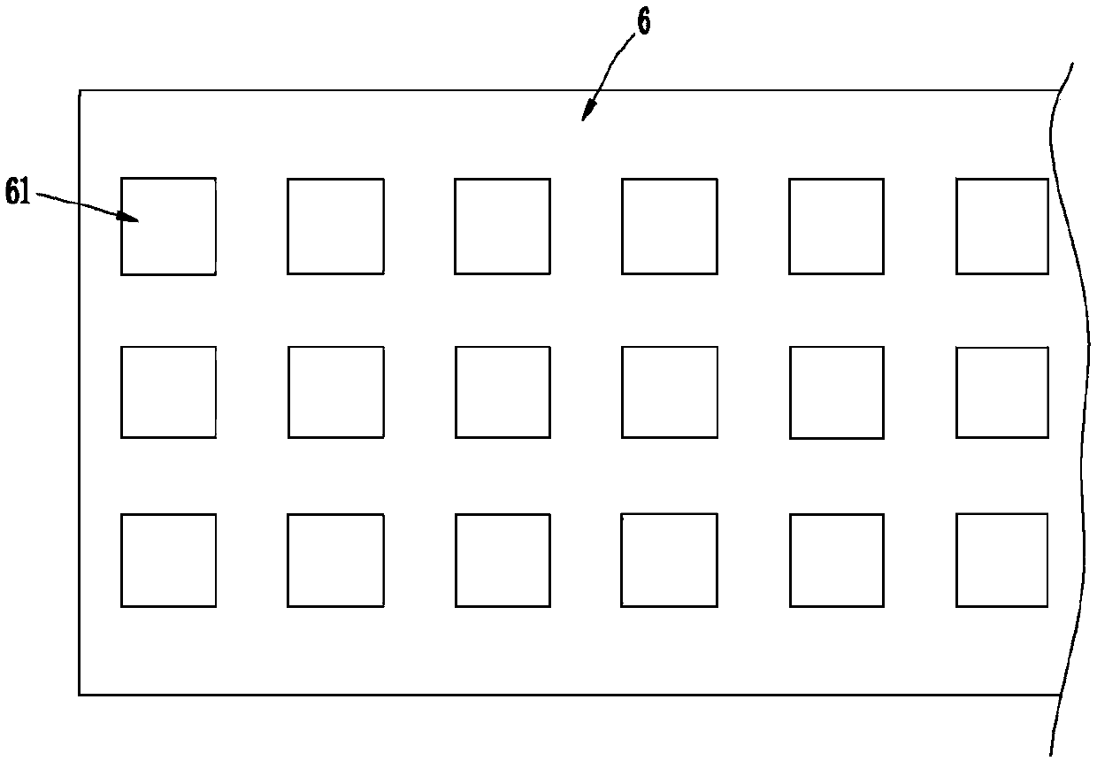
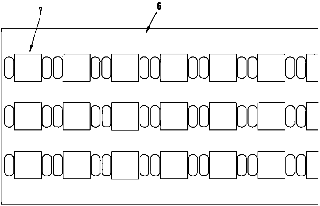
[0033] See attached Figures 1 to 6 As shown, the present embodiment provides a method for making a radio frequency payment module, which includes the following steps:

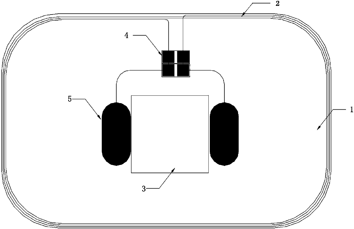
[0034] (1) See attached figure 1 As shown, first design a circuit board with a thickness of more than 0.3mm (generally between 0.3mm and 1mm). Design a coil with a debugging capacitor and a Q value adjusting resistor on the front and back. The minimum distance between the outermost edge of the coil and the edge of the circuit board is controlled above 0.3mm, and the resonant frequency of the coil is adjusted within the range of 13.5HZ±0.5 by using the debugging capacitor. After debugging the Q value through the resistance, it is within the standard range;

[0035] (2) Set pad contacts on the circuit board according to the size of the soldering contacts of the chip ...


PUM

PropertyMeasurementUnit
Thicknessaaaaaaaaaa

Abstract

The invention discloses a radio frequency payment module, relating to the technical field of smart cards, the radio frequency payment module comprises a circuit board, a double-sided conductive tape and a chip module; a combination mode of the conductive adhesive tape and the PCB is adopted; the problems that special-shaped molds are diversified and cannot be produced on a large scale can be effectively solved; particular, the PCB and the chip module are combined and assembled through a double-sided conductive adhesive tape. the plurality of chip modules are distributed on the carrier tape; forming carrier tape module, meanwhile, a conductive adhesive tape matched with the carrier tape module in length and width is adopted; a plastic package position, corresponding to the chip module, on the conductive adhesive tape is hollowed out; the carrier tape module and the conductive adhesive tape are hot-pressed and fixed through hot-pressing equipment; the method comprises the steps that a carrier tape module stamping die is used for stamping a carrier tape to form gum modules, the formed gum modules separate rubber through equipment subsequently, the chip modules on the carrier tape areseparated into single gum modules through the carrier tape module stamping die, finally, the multiple formed single gum modules are connected with a circuit board, and the payment module is formed.

Description

technical field [0001] The invention relates to the technical field of smart cards, in particular to a radio frequency payment module and a manufacturing method thereof. Background technique [0002] As the application of cards becomes more and more extensive, the market demand has also changed from the original ordinary smart cards to multi-form special-shaped cards. For example, the pattern has special-shaped cards such as twelve zodiac signs, Chinese knots, and poems. Most of these special-shaped cards use wire + lamination and PCB board welding. In terms of design, they can only be suitable for some simple plane special-shaped structures, such as Line + lamination method, if special-shaped cards need to be produced, the production cost will increase, and special-shaped cards of different shapes need to use different stamping dies. The PCB board welding method cannot be mass-produced and the height of the solder joints changes with personnel changes. The structural requi...

Claims


Application Information

Patent Timeline
IPC IPC(8): G06K19/077H01L21/603H01L23/498
Inventor 彭朝跃
Owner WATCHDATA SYST
Learn More