
Gate driving unit, gate driving method, gate driving circuit and display device

A gate driving and circuit technology, applied in the fields of gate driving method, gate driving unit, gate driving circuit and display device, can solve the problems of inability to guarantee the driving capability of the gate driving unit and the inability to maintain the pull-up node, etc. To achieve the effect of ensuring the driving ability

Active Publication Date: 2019-05-28
HEFEI XINSHENG OPTOELECTRONICS TECH CO LTD +1
View PDF25 Cites 0 Cited by
  • Summary
  • Abstract
  • Description
  • Claims
  • Application Information

AI Technical Summary

Problems solved by technology

[0003] The main purpose of the present invention is to provide a gate drive unit, a gate drive method, a gate drive circuit and a display device, which solve the problem that the potential of the pull-up node cannot be maintained in the output stage in the prior art, so that the gate drive unit cannot be guaranteed. drive ability problem

Method used


Image

  • Gate driving unit, gate driving method, gate driving circuit and display device
  • Gate driving unit, gate driving method, gate driving circuit and display device
  • Gate driving unit, gate driving method, gate driving circuit and display device

Examples


Embodiment approach

[0049] According to another specific implementation manner, the transistor connected to the pull-up node in the pull-up node pull-down circuit may be an n-type transistor, and the second predetermined voltage range is less than or equal to 0; or,

[0050] The transistor connected to the pull-up node in the pull-up node pull-down circuit may be a p-type transistor, and the second predetermined voltage range is greater than or equal to 0.

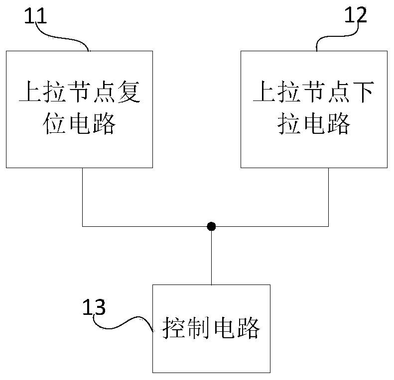
[0051] Specifically, the pull-up node reset circuit may include a pull-up node reset transistor;

[0052] The control pole of the pull-up node reset transistor is connected to the reset terminal, the first pole of the pull-up node reset transistor is connected to the pull-up node, and the second pole of the pull-up node reset transistor is connected to the first voltage terminal connect;

[0053] The control circuit includes a voltage supply circuit;

[0054] The voltage supply circuit is used to provide a first voltage to the first voltage...


PUM


Abstract

The invention provides a gate driving unit, a gate driving method, a gate driving circuit and a display device. The grid driving unit comprises a pull-up node reset circuit, a pull-up node pull-down circuit and a control circuit; The control circuit is used for controlling the gate-source voltage of the transistor connected with the pull-up node in the pull-up node reset circuit to be within a first preset voltage range and controlling the gate-source voltage of the transistor connected with the pull-up node in the pull-down circuit of the pull-up node to be within a second preset voltage range at an output stage. According to the invention, the potential of the pull-up node can be well maintained in the output stage, and the driving capability of the grid driving unit is ensured.

Description

technical field [0001] The present invention relates to the technical field of display driving, in particular to a gate driving unit, a gate driving method, a gate driving circuit and a display device. Background technique [0002] When the existing gate drive unit is working, when the pulse signal at the input terminal arrives, it charges the pull-up node, and then when the potential of the input signal is lowered, it maintains the potential of the pull-up node. When the row clock signal arrives, Due to the bootstrapping effect, the potential of the pull-up node is further pulled up. However, in the real process, due to the large number of transistors electrically connected to the pull-up node, and in the case of the existing GOA (Gate On Array, gate drive circuit arranged on the array substrate) architecture design, the pull-up node The gate-source voltage Vgs of the connected transistor is generally above 0V (taking the transistor as an n-type transistor as an example), ...

Claims


Application Information

Patent Timeline
Patent Type & Authority Applications(China)
IPC IPC(8): G09G3/20
Inventor 陈宇霆杨通木素真
Owner HEFEI XINSHENG OPTOELECTRONICS TECH CO LTD
Features
  • Generate Ideas
  • Intellectual Property
  • Life Sciences
  • Materials
  • Tech Scout
  • Unparalleled Data Quality
  • Higher Quality Content
  • 60% Fewer Hallucinations
Learn More