
A control method and system for intelligent optical distribution measurement

A control method and control system technology, applied in the control method and system field of intelligent optical distribution measurement, can solve the problems of optical fiber communication quality degradation, fiber cladding shedding, time-consuming and other problems, and achieve remote switching control, fast and safe Reliable switching and guaranteed normal operation

Active Publication Date: 2019-05-28
GLOBAL ENERGY INTERCONNECTION RES INST CO LTD +6
View PDF6 Cites 5 Cited by
  • Summary
  • Abstract
  • Description
  • Claims
  • Application Information

AI Technical Summary

Problems solved by technology

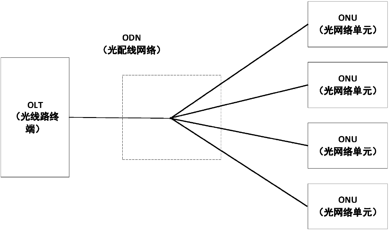
Among them, the tree structure is the most commonly used. Since the optical distribution frame, optical transfer box, optical splitter, and optical fiber in the ODN have been placed in the field for a long time, the influence of wind, rain, and sun may cause the connector of the optical fiber to loosen and the package of the optical fiber to become loose. Layer shedding, fiber breakage, etc., lead to a decrease in the quality of optical fiber communication or even communication interruption. If it is not discovered in time, it will not only easily cause user communication interruption, but also greatly increase the difficulty of system maintenance.
Simply relying on manual maintenance consumes a lot of time and may not be able to obtain satisfactory results
[0004] With the increasing scale of ODN construction and more and more resources, the traditional ODN resource management methods have many uncoordinated disadvantages
When the user network fails, the ODN network will be repaired. This passive operation and maintenance method often leads to a decline in the quality of the entire network.

Method used


Image

  • A control method and system for intelligent optical distribution measurement
  • A control method and system for intelligent optical distribution measurement
  • A control method and system for intelligent optical distribution measurement

Examples


Embodiment Construction

[0033] The specific implementation manners of the present invention will be further described in detail below in conjunction with the accompanying drawings.

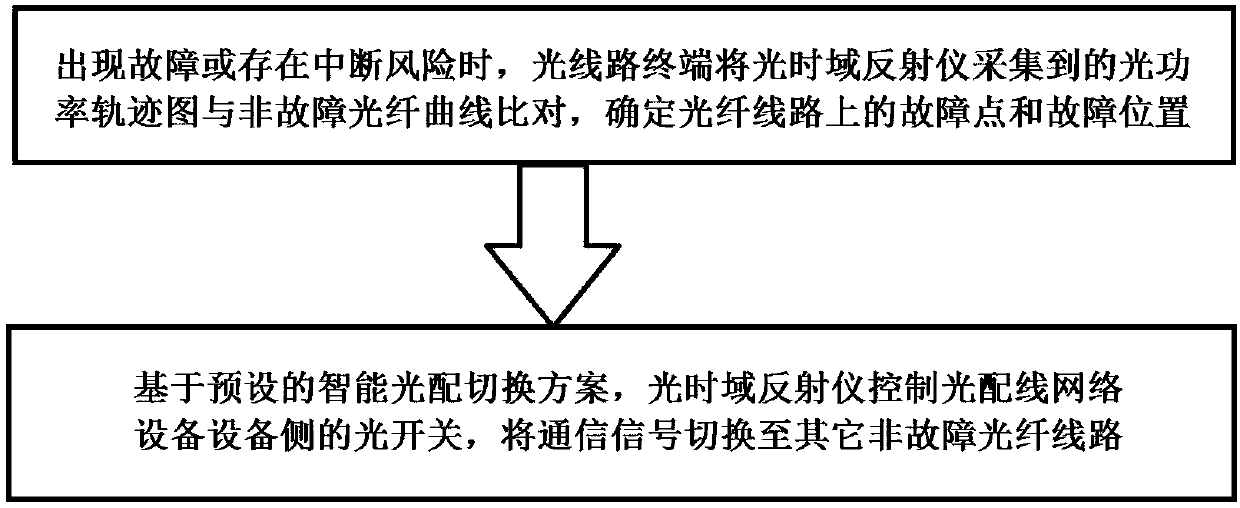
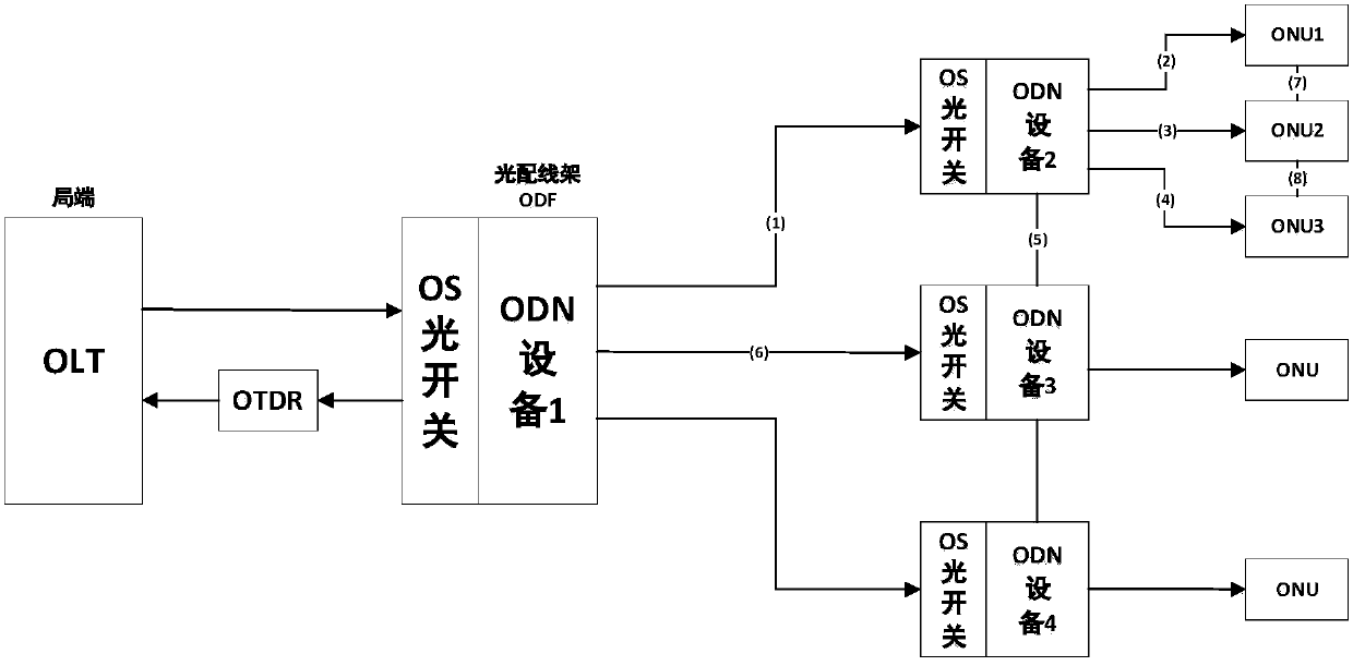
[0034] Such as figure 1 As shown, the control method of the present invention includes the steps of: using an optical time domain reflectometer OTDR to detect each optical fiber line connected to the electric passive optical fiber network PON; The line terminal OLT compares the optical power trajectory collected by the optical time domain reflectometer OTDR with the normal optical fiber curve to determine the fault point and fault location on the optical fiber line; based on the preset intelligent optical distribution switching scheme, the optical time domain reflectometry The OTDR controls the optical switch OS on the equipment side of the optical distribution network equipment ODN1 to switch the communication signal to other healthy optical fiber lines.

[0035] Such as figure 2 As shown, the PON structure of the pres...


PUM


Abstract

The invention provides a control method and system for intelligent optical distribution measurement, and the method comprises the steps: enabling an optical line terminal (OLT) to compare an optical power track diagram collected by an optical time domain reflectometer (OTDR) with a non-fault optical fiber curve when an optical fiber line has a fault or an interruption risk exists, and determininga fault point and a fault position on the optical fiber line; and based on a preset intelligent optical distribution switching scheme, the OTDR controls an optical switch OS on the first optical distribution network equipment ODN1, and switches the communication signal to other non-fault optical fiber lines. According to the invention, the acquired optical power track diagram is compared with thereference curve of the optical fiber in normal operation; The fault information is determined, the optical line terminal (OLT) starts a preset switching plan, the equipment is guided to timely changethe path, the state information of the equipment is reported to the optical line terminal (OLT), and rapid, safe and reliable switching of the optical communication signals is realized.

Description

technical field [0001] The invention belongs to the technical field of intelligent optical distribution, and in particular relates to a control method and system for intelligent optical distribution measurement. Background technique [0002] In recent years, the power optical cable network has been the main mode of the power communication network. With the application of optical fiber transmission in the power communication network, the automatic management level of massive optical fibers needs to be improved urgently. At present, the optical cable monitoring system cannot realize the timely monitoring of dozens of lines. When the power optical cable network fails, it will directly affect the safety and stability of the production and operation of the entire power system. Once the communication of important links fails, it will cause huge losses to the power grid. . Among them, the power optical fiber distribution communication network is an important part of the power tran...

Claims


Application Information

Patent Timeline
IPC IPC(8): H04B10/071H04B10/07H04B10/038
Inventor 孙晓艳吕立冬喻强邓辉张增华李炳林刘川姚继明钟成崔力民郭经红高鹏辛国良葛维春罗桓桓周桂平王英杰王小辉
Owner GLOBAL ENERGY INTERCONNECTION RES INST CO LTD
Learn More