
Slotted hole machining method and circuit board

A processing method and circuit board technology, applied in printed circuits, printed circuit manufacturing, electrical components, etc., can solve problems such as large differences in material distribution, slot deformation, and drill offset.

Inactive Publication Date: 2019-05-28
GUANGZHOU FASTPRINT CIRCUIT TECH +1
View PDF6 Cites 8 Cited by
  • Summary
  • Abstract
  • Description
  • Claims
  • Application Information

AI Technical Summary

Problems solved by technology

[0002] In the traditional slot hole processing technology, it is necessary to drill multiple times, and at the same time different drill holes intersect. When the second hole is drilled, because the previous hole has been drilled, when the next hole is drilled, the material around the drill bit The distribution is quite different, which can easily lead to uneven force on the drill when drilling, and the drill will deviate in the direction of the first hole, resulting in quality problems such as deformation, burrs, and oversized holes in the processed slots.

Method used


Image

  • Slotted hole machining method and circuit board
  • Slotted hole machining method and circuit board

Examples


Embodiment Construction

[0026] In order to facilitate the understanding of the present invention, the present invention will be described more fully below with reference to the associated drawings. Preferred embodiments of the invention are shown in the accompanying drawings. However, the present invention can be embodied in many different forms and is not limited to the embodiments described herein. On the contrary, the purpose of providing these embodiments is to make the disclosure of the present invention more thorough and comprehensive.

[0027] It should be noted that when an element is referred to as being “fixed” to another element, it can be directly on the other element or there can also be an intervening element. When an element is referred to as being "connected to" another element, it can be directly connected to the other element or intervening elements may also be present. The terms "vertical," "horizontal," "left," "right," and similar expressions are used herein for purposes of ill...


PUM


Abstract

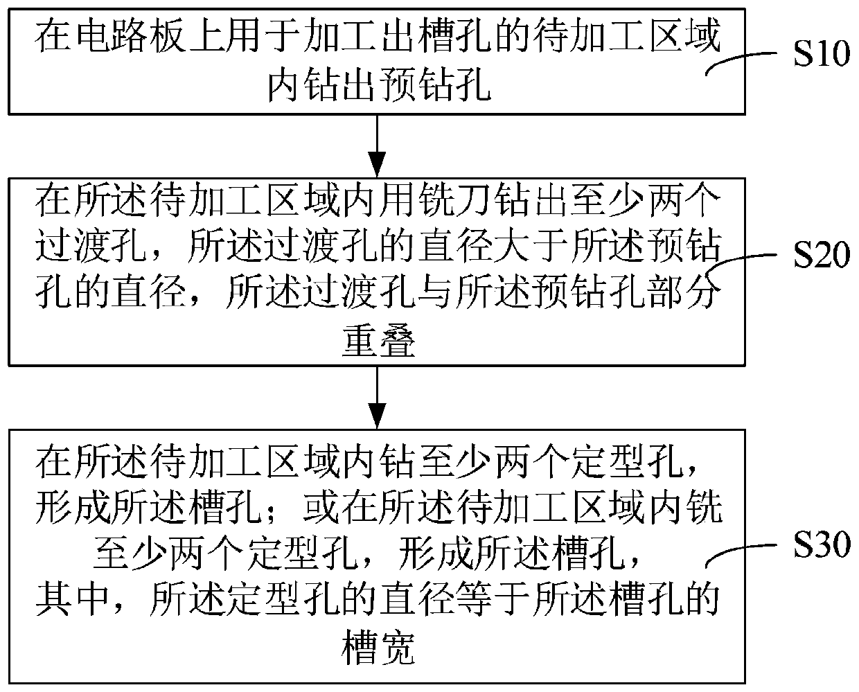
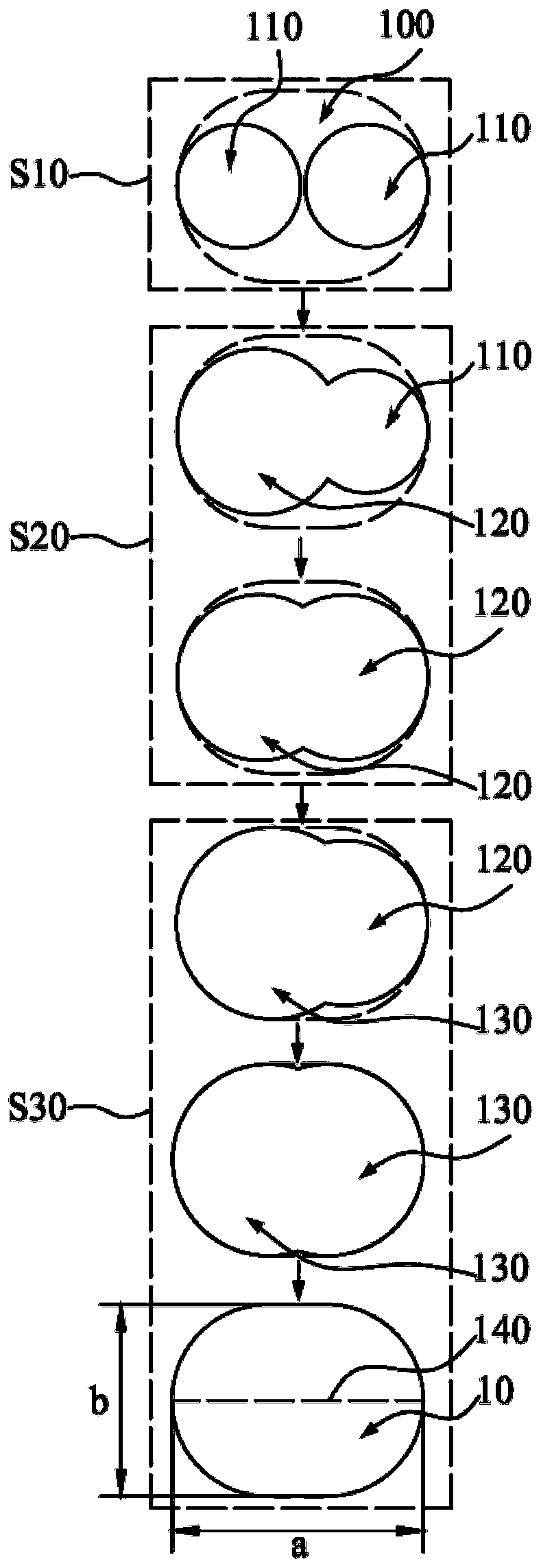
The invention discloses a slotted hole machining method and a circuit board. The slotted hole machining method comprises the following steps that pre-drilled holes are drilled in a to-be-machined area, used for machining a slotted hole, of the circuit board; and at least two transition holes are drilled in the to-be-machined area by a milling cutter, wherein the diameter of each transition hole islarger than that of the corresponding pre-drilled hole, and the transition holes and the pre-drilled holes are partially overlapped. According to the slotted hole machining method, chippings generated in the milling process can be discharged from the pre-drilled holes; meanwhile, part of materials in the to-be-machined area can be removed in the milling process; when a slotted hole is formed in the to-be-machined area in the follow-up process, materials required to be removed in the to-be-processed area are reduced; the situation that a cutter head is stressed unevenly during machining can bereduced, the cutter head cannot deviate, the product quality is improved, and in the milling process, even if materials around the milling cutter are distributed unevenly, due to the fact that the milling cutter is high in rigidity, not prone to stress deviation and good in machining effect, subsequent machining cannot be affected, and the product quality can be improved.

Description

technical field [0001] The invention relates to the technical field of mechanical processing, in particular to a slot hole processing method and a circuit board. Background technique [0002] In the traditional slot hole processing technology, it is necessary to drill multiple times, and at the same time different drill holes intersect. When the second hole is drilled, because the previous hole has been drilled, when the next hole is drilled, the material around the drill bit The distribution is quite different, which can easily lead to uneven force on the drill when drilling, and the drill will deviate in the direction of the first hole, resulting in quality problems such as deformation, burrs, and oversized holes in the processed slot. Contents of the invention [0003] Based on this, the present invention overcomes the defects of the prior art and provides a slot hole processing method and a circuit board which can improve product quality. [0004] Its technical scheme...

Claims


Application Information

Patent Timeline
Patent Type & Authority Applications(China)
IPC IPC(8): H05K3/00
Inventor 杨烈文陈黎阳
Owner GUANGZHOU FASTPRINT CIRCUIT TECH
Learn More