Vibration anti-holding shaft concrete mixer

A concrete mixer and anti-locking technology, which is applied in the direction of cement mixing devices, clay preparation devices, chemical instruments and methods, etc., can solve the problems of affecting the use of the deceleration device, affecting the output efficiency, increasing the burden on the stirring shaft, etc., and prolonging the service life , High working efficiency, uniform mixing effect

Inactive Publication Date: 2019-05-31
KOORUN INTELLIGENCE TECH CO LTD
View PDF0 Cites 3 Cited by
  • Summary
  • Abstract
  • Description
  • Claims
  • Application Information

AI Technical Summary

Problems solved by technology

[0002] At present, with the continuous development of China's economic construction and the acceleration of urbanization, China's urban infrastructure and real estate development have developed rapidly, which has promoted the rapid increase in concrete production. Concrete mixer is a high-efficiency concrete Mixing machinery is widely used in concrete projects such as high-rise buildings, coal mines, mines, tunnels, railways, highways, bridges and culverts, ports, water conservancy, electric power, and national defense projects. Fully mix with water. The concrete mixer is mainly composed of a mixing drum, a feeding and unloading mechanism and a power device. Usually, there is a mixing drum on the mixer, and a stirring shaft is installed in the mixing drum. When cement, sand and gravel aggregate When raw materials such as mixed with water are added to the mixing tank, during the rotation of the mixing blade, the vibration of the mixing blade will be transmitted to the output shaft of the motor through the deceleration device, which will affect the use of the deceleration device and the motor, and reduce the service life. It does not meet the uniformity requirements of the concrete, and a thick layer of concrete will solidify on the mixing shaft and inner surface wall of the concrete mixer, which will increase the burden on the mixing shaft, increase the probability of shaft holding accidents, and greatly affect the output efficiency

Method used


Image

  • Vibration anti-holding shaft concrete mixer

Examples


Embodiment Construction

[0012] The following will clearly and completely describe the technical solutions in the embodiments of the present invention with reference to the accompanying drawings in the embodiments of the present invention. Obviously, the described embodiments are only some, not all, embodiments of the present invention. Based on the embodiments of the present invention, all other embodiments obtained by persons of ordinary skill in the art without making creative efforts belong to the protection scope of the present invention.

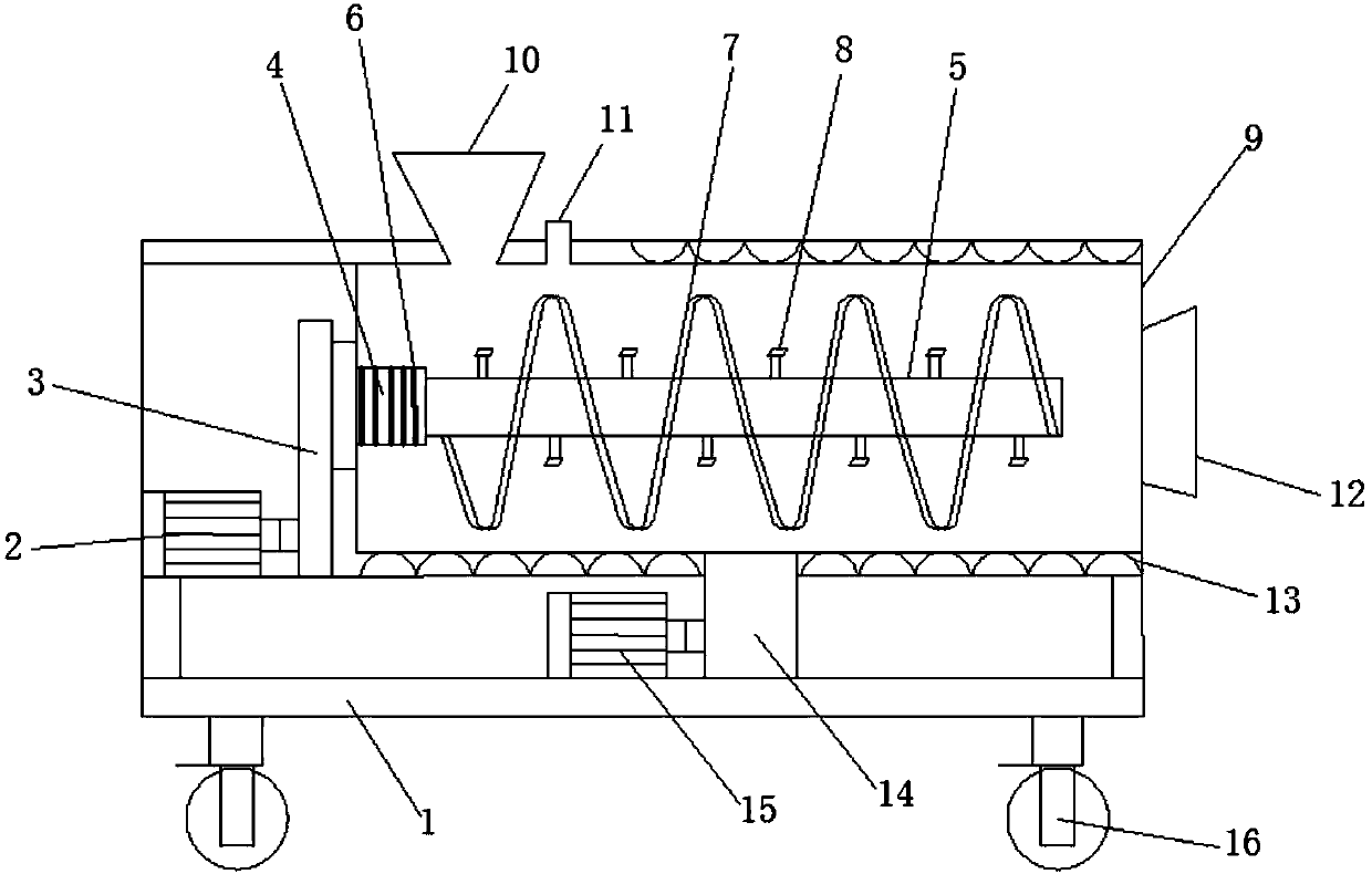
[0013] The present invention provides such figure 1 A vibrating anti-lock shaft concrete mixer shown includes a support 1 and a mixing bucket 9. The bottom of the support 1 is provided with a walking wheel 16 for easy movement and placement. The support 1 is provided with a drive motor 2, and the drive The output shaft of the motor 2 is connected to the input end of the deceleration device 3, and the output shaft of the deceleration device 3 is connected to th...


PUM


Abstract

The invention discloses a vibration anti-holding shaft concrete mixer. The concrete mixer comprises a support and a stirring barrel, a walking wheel is arranged at the bottom of the support, a drivingmotor is arranged on the support, an output shaft of the driving motor is connected with the input end of the speed reducing device, the output shaft of the speed reducing device is connected with astirring shaft through a coupling, the coupling is provided with a damping spring, a spiral stirring blade and a stirring knife are arranged on the stirring shaft, a feeding hole and a water inlet areformed in the upper end of the stirring barrel, and a discharging opening is formed in the side surface of the stirring barrel, elastic steel sheets are arranged on the upper side and the lower sideof the stirring barrel, the outer wall of the stirring barrel is connected with an eccentric wheel device, and the eccentric wheel device is connected with a vibration motor. The vibration anti-holding shaft concrete mixer can prolong the service life of the driving motor, meanwhile, the concrete cannot be subjected to a shaft holding accident due to condensation on the barrel wall and the stirring shaft, the operation is smooth, and the working efficiency is high.

Description

technical field [0001] The invention belongs to the technical field of building construction equipment, and in particular relates to a vibration anti-lock shaft concrete mixer. Background technique [0002] At present, with the continuous development of China's economic construction and the acceleration of urbanization, China's urban infrastructure and real estate development have developed rapidly, which has promoted the rapid increase in concrete production. Concrete mixer is a high-efficiency concrete Mixing machinery is widely used in concrete projects such as high-rise buildings, coal mines, mines, tunnels, railways, highways, bridges and culverts, ports, water conservancy, electric power, and national defense projects. Fully mix with water. The concrete mixer is mainly composed of a mixing drum, a feeding and unloading mechanism and a power device. Usually, there is a mixing drum on the mixer, and a stirring shaft is installed in the mixing drum. When the cement, sand ...

Claims


Application Information

Patent Timeline
Patent Type & Authority Applications(China)
IPC IPC(8): B28C5/14B28C5/48B28C5/08
Inventor 张锦
Owner KOORUN INTELLIGENCE TECH CO LTD
Why Eureka
Try Eureka