
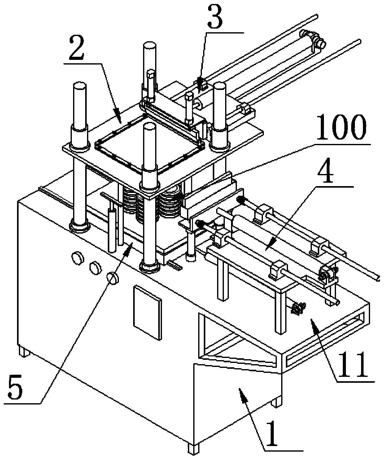
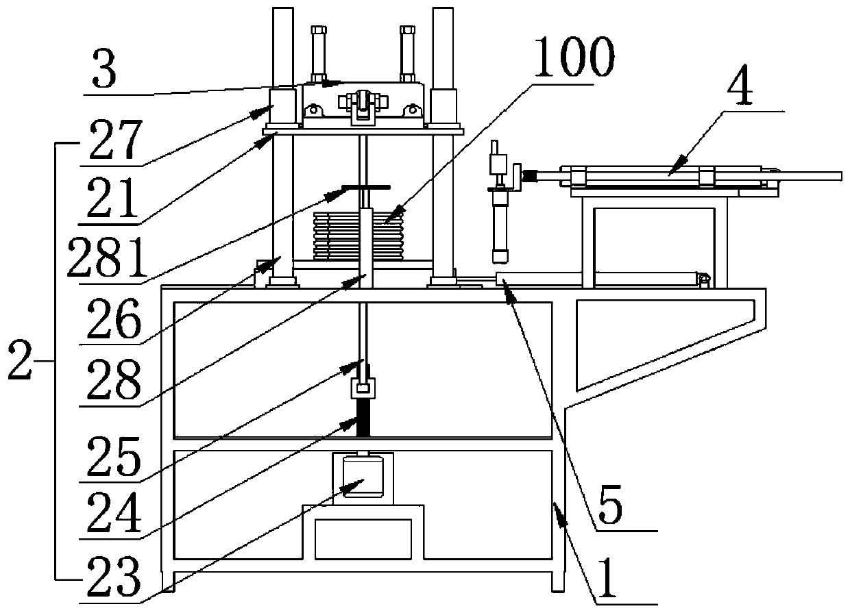
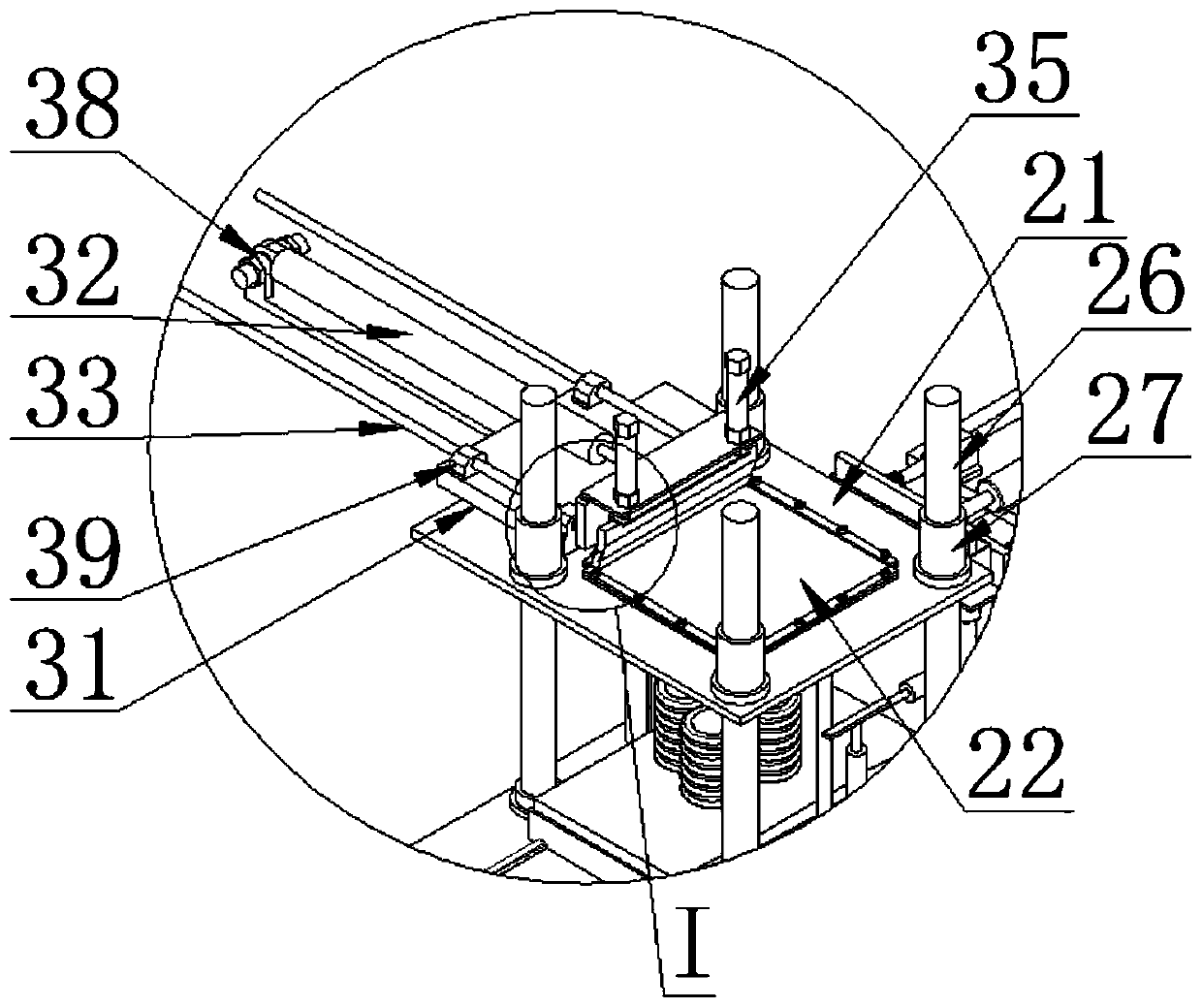
Screen printing equipment for coating end face of ceramic vacuum tube

A technology of screen printing and vacuum tube, applied in screen printing machine, printing, printing machine and other directions, can solve problems such as low production efficiency, and achieve the effect of improving printing efficiency

Active Publication Date: 2019-05-31
HUBEI XINSHIQI ELECTROCERAMICS TECH CO LTD
View PDF9 Cites 10 Cited by
  • Summary
  • Abstract
  • Description
  • Claims
  • Application Information

AI Technical Summary

Problems solved by technology

In the industry, screen printing equipment is usually used to print the metal paste on one end face of the ceramic vacuum tube through a screen. After drying the metal paste on the end face, replace the screen, and use a slightly thinner metal paste than the previous pass to repeat on the ceramic vacuum tube. Print again on the end surface of the ceramic vacuum tube. The purpose of the repeated printing is to correct and fill the defects of the paste surface in the first printing with the second pass of thinner metal paste. After drying again, use the same method to print the ceramic vacuum tube. The other end face, and only one end face of a product can be printed at a time. When feeding and unloading, it is necessary to manually place the ceramic vacuum tube on the pallet, adjust the position before printing, resulting in low production efficiency

Method used


Image

  • Screen printing equipment for coating end face of ceramic vacuum tube
  • Screen printing equipment for coating end face of ceramic vacuum tube
  • Screen printing equipment for coating end face of ceramic vacuum tube

Examples


Embodiment Construction

[0030] In order to enable those skilled in the art to better understand the technical solution of the present invention, the present invention will be described in detail below in conjunction with the accompanying drawings. The description in this part is only exemplary and explanatory, and should not have any limiting effect on the protection scope of the present invention. .

[0031] It should be noted that like numerals and letters denote similar items in the following figures, therefore, once an item is defined in one figure, it does not require further definition and explanation in subsequent figures.

[0032] It should be noted that the orientation or positional relationship indicated by the terms "center", "upper", "lower", "left", "right", "vertical", "horizontal", "inner" and "outer" are Based on the orientation or positional relationship shown in the drawings, or the orientation or positional relationship that the inventive product is usually placed in use, it is onl...


PUM


Abstract

The invention discloses screen printing equipment for coating the end face of a ceramic vacuum tube. The screen printing equipment comprises a lifting mechanism, a printing mechanism used for printingmetal paste on the end face of the ceramic vacuum tube, a paste collecting mechanism used for recycling the metal paste remaining on a silk screen during printing operation, and feeding and discharging mechanisms used for inputting and outputting a plurality of ceramic vacuum tubes during operation. According to the screen printing equipment, automatic feeding and discharging of a plurality of products can be achieved through the feeding and discharging mechanisms, and the simultaneous coating operation of the multiple ceramic vacuum tubes is achieved; compared with traditional equipment thatcan be used for printing one ceramic vacuum tube only every time, the screen printing equipment has the advantages that the printing efficiency is improved greatly; the metal paste remaining on the silk screen is recycled into a paste collecting tank through a paste collecting scraper of the paste collecting mechanism, and the recycling of materials is achieved; and the waste of the materials canbe reduced effectively.

Description

technical field [0001] The invention relates to a screen printing device for coating the end surface of a ceramic vacuum tube. Background technique [0002] At present, metal paste coating is one of the key technologies for the metallization of ceramic vacuum tubes, and the coated paste is required to have good flatness, strong consistency, and high density after high-temperature firing. In the industry, screen printing equipment is usually used to print the metal paste on one end face of the ceramic vacuum tube through a screen. After drying the metal paste on the end face, replace the screen, and use a slightly thinner metal paste than the previous pass to repeat on the ceramic vacuum tube. Print again on the end surface of the ceramic vacuum tube. The purpose of the repeated printing is to correct and fill the defects of the paste surface in the first printing with the second pass of thinner metal paste. After drying again, use the same method to print the ceramic vacuum ...

Claims


Application Information

Patent Timeline
IPC IPC(8): B41F15/08B41F15/42B41F15/44B41F15/18
Inventor 陈脉陈舒庆
Owner HUBEI XINSHIQI ELECTROCERAMICS TECH CO LTD
Features
  • Generate Ideas
  • Intellectual Property
  • Life Sciences
  • Materials
  • Tech Scout
  • Unparalleled Data Quality
  • Higher Quality Content
  • 60% Fewer Hallucinations
Learn More