New-energy-vehicle emergency brake device with combination switch and control method thereof

A combined switch and emergency braking technology, which is applied to manual starting devices, vehicle parts, transportation and packaging, etc., can solve the problems of low safety of the anti-accidental accelerator device and no effective stopping measures for the car, so as to improve safety. Effect

Active Publication Date: 2019-05-31
ZHEJIANG LEAPMOTOR TECH CO LTD
View PDF5 Cites 3 Cited by
  • Summary
  • Abstract
  • Description
  • Claims
  • Application Information

AI Technical Summary

Problems solved by technology

[0004] The technical problem to be solved by the present invention is: the safety of the current anti-acceleration device is not high, and the technical problem that the car has no effective stop measures when the driver accidentally steps on the accelerator

Method used


Image

  • New-energy-vehicle emergency brake device with combination switch and control method thereof
  • New-energy-vehicle emergency brake device with combination switch and control method thereof
  • New-energy-vehicle emergency brake device with combination switch and control method thereof

Examples


Embodiment 1

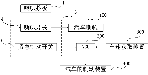
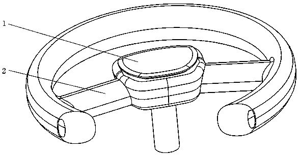
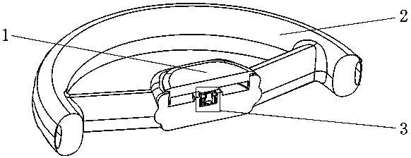
[0023] A kind of combined switch type emergency braking device for new energy vehicles, such as figure 1 As shown, it is a schematic block diagram of the combined switch type emergency braking device circuit in the embodiment, as figure 2 As shown, it is a schematic diagram of the three-dimensional structure of the steering wheel of a car, such as image 3 As shown, it is a schematic diagram of the installation position of the combination switch in embodiment one. This embodiment includes a combination switch 3, a VCU200 and a vehicle speed acquisition device 300. The combination switch 3 is installed between the horn press plate 1 and the steering wheel 2 of the automobile. 2 is fixedly connected, and the combination switch 3 includes a horn switch 4 and an emergency brake switch 6. The trigger strokes of the horn switch 4 and the emergency brake switch 6 are all within the stroke of the horn press plate 1 of the car, and the trigger stroke of the horn switch 4 is shorter th...

Embodiment 2

[0028] This embodiment adds a new emergency brake trigger device, such as Figure 5 As shown, it is a schematic diagram of the three-dimensional structure of the automobile steering wheel in embodiment two, as Figure 6 As shown, it is a schematic diagram of the structure of the air-filled chamber in Embodiment 2, such as Figure 7Shown is the schematic diagram of the trigger circuit of Embodiment 2. In this embodiment, the steering wheel 2 gripping force detector is installed on the steering wheel 2. The steering wheel 2 gripping force detector detects the force of the driver holding the steering wheel 2, and the steering wheel 2 is gripped tightly. The force detector is connected to the input end of the trigger circuit, the trigger circuit is connected to the VCU200, and the trigger circuit sends a braking signal to the VCU200 when the output voltage of the force detector exceeds the threshold when the steering wheel 2 is gripped tightly. The trigger circuit includes a resi...


PUM


Abstract

The invention relates to the technical field of automobile safety, in particular to a new-energy-vehicle emergency brake device with a combination switch and a control method thereof. The device includes the combination switch, a VCU and a vehicle speed acquisition device, the combination switch is fixedly connected with a steering wheel and includes a horn switch and an emergency brake switch, the triggering stokes of the horn switch and the emergency brake switch are both within the stoke of a horn press board of an automobile, and the triggering stoke of the horn switch is closer to that ofthe horn press board relative to the triggering stoke of the emergency brake switch. The control method includes the following steps that 1, as the emergency brake switch is triggered, the VCU analyzes the vehicle speed obtained by the vehicle speed acquisition device through comparison; 2, the device prompts people for misoperation if the speed of the automobile does not exceed the set upper limit of the vehicle speed; 3, the VCU sends a signal to the brake device of the automobile to make the automobile braked. The device has the advantages that the emergency brake device is arranged underan automobile horn to avoid the situation that a driver confuses a brake pedal and an accelerator pedal, and the safety of the automobile is improved.

Description

technical field [0001] The invention relates to the technical field of automobile safety, in particular to an emergency braking device with a combined switch for a new energy vehicle and a control method thereof. Background technique [0002] The principle of the braking system is to create a huge friction force, which converts the kinetic energy of the vehicle into heat energy. As we all know, energy can neither be created nor destroyed, it can only be transformed from one form to another, or transferred from one object to another. In the process of transformation or transfer, the total amount of energy is not Change. The car converts chemical energy into thermal energy and kinetic energy during acceleration, and the brake system converts the kinetic energy of the car into heat energy and emits it into the air when braking. It may take 10 seconds for a car to accelerate from a standstill to a speed of 100 kilometers per hour, but it may only take a few seconds to brake fr...

Claims


Application Information

Patent Timeline
IPC IPC(8): B60T7/10B60R16/00B60R16/023
Inventor 宋建勋
Owner ZHEJIANG LEAPMOTOR TECH CO LTD
Why Eureka
Try Eureka