
Hypersonic aircraft and thermal protection structure and coolant circulating system thereof

A thermal protection structure, hypersonic technology, applied in the direction of heat reduction structure, aircraft parts, air handling equipment, etc., can solve the problems of small deformation of the leading edge of the aircraft aerodynamic rudder, poor aerodynamic load bearing capacity, material failure flight speed, etc., to achieve Solve the problem of material failure, eliminate the effect of localized high temperature, good aerodynamic characteristics and operating characteristics

Pending Publication Date: 2019-05-31
CENT SOUTH UNIV
View PDF22 Cites 9 Cited by
  • Summary
  • Abstract
  • Description
  • Claims
  • Application Information

AI Technical Summary

Problems solved by technology

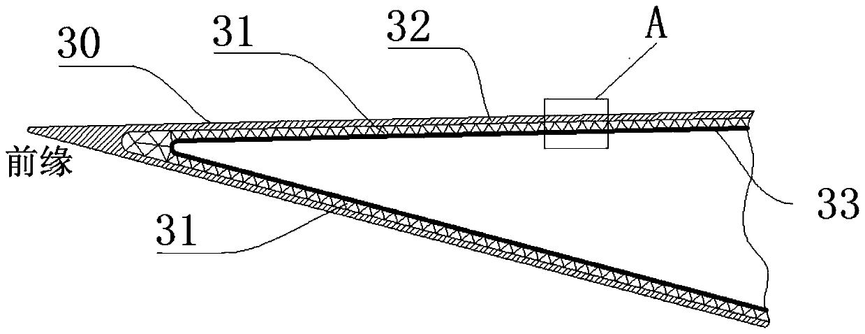
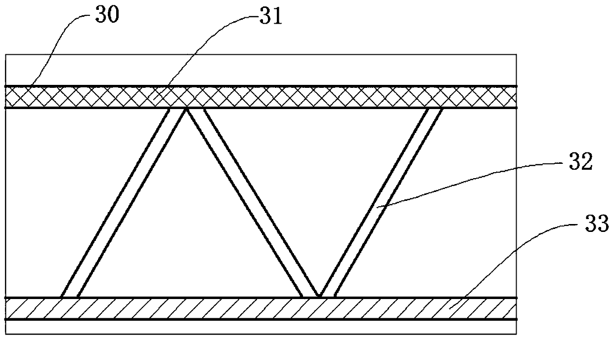
[0007] The purpose of the present invention is to provide a heat protection structure for the leading edge of the aerodynamic rudder of an aircraft, especially to provide an integrated heat protection structure for the leading edge of the aerodynamic rudder of a hypersonic aircraft, which can reduce the deformation of the leading edge of the aerodynamic rudder of the aircraft and reduce the heat flux density. Small, maintains the aerodynamic characteristics of the aircraft's high lift-to-drag ratio and the operability of the aerodynamic rudder, solves the problem of material failure caused by the large heat flow at the leading edge of the aerodynamic rudder of the aircraft and the problem of poor aerodynamic load capacity caused by high flight speed, and avoids the problem of aerodynamic rudder front The extreme distribution of the edge temperature realizes the long-term heat insulation of the aircraft

Method used


Image

  • Hypersonic aircraft and thermal protection structure and coolant circulating system thereof
  • Hypersonic aircraft and thermal protection structure and coolant circulating system thereof
  • Hypersonic aircraft and thermal protection structure and coolant circulating system thereof

Examples


Embodiment Construction

[0034] Hypersonic vehicles are an important direction for the development of future aircraft. Hypersonic vehicles require a high lift-to-drag ratio and the leading edges of the wings and aerodynamic rudders are sharp. The sharp leading edge is also subjected to local ultra-high heat flow heating, resulting in extremely uneven temperature distribution in different parts of the aerodynamic rudder. This harsh thermal environment poses a severe challenge to traditional heat-resistant structures. Moreover, hypersonic vehicles also have to bear large aerodynamic loads during flight. Most of the current designs are cold structure designs, and there is no comprehensive design of heat-resistant structures and load-bearing structures, which greatly increases the thermal protection structure of the aircraft's aerodynamic rudder. The quality of the aircraft reduces the aerodynamic characteristics and maneuverability of the aircraft.

[0035]The embodiment of the present invention designs ...


PUM


Abstract

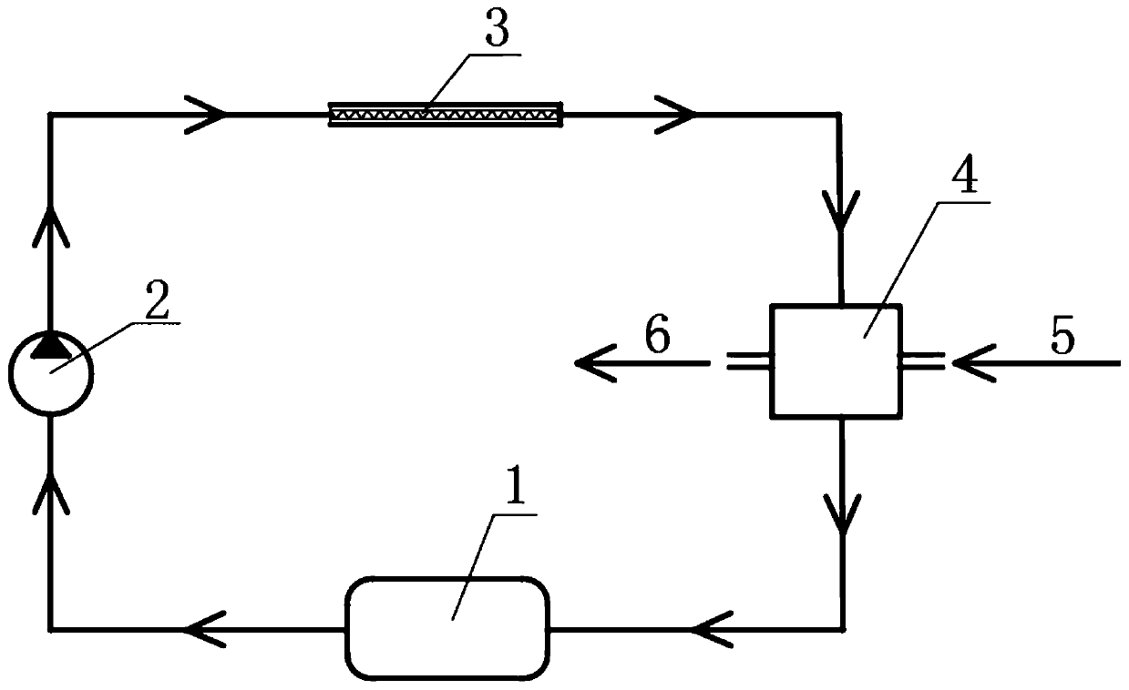
The invention provides an integrated thermal protection structure for the leading edge of a hypersonic aircraft pneumatic rudder, which is integrally designed and comprises a heat protection skin, a heat pipe, a heat absorption device and a heat insulation layer, wherein the heat protection skin is arranged on the outer surface of the leading edge of the pneumatic rudder; the heat absorption device is arranged on the inner surface of the heat protection skin; the heat pipe is fixedly connected with the heat absorption device; the heat pipe is arranged on the inner surface of the heat absorption device; and the heat insulation layer is fixedly arranged on the inner surface of the heat pipe. The invention also provides a coolant circulating system and a hypersonic aircraft. According to theinvention, the deformation of the leading edge of the aircraft pneumatic rudder is small, the heat flow density is small, the aerodynamic characteristic of the aircraft with high lift-resistance ratioand the operability of the pneumatic rudder are kept, the problems of material failure caused by large heat flow of the leading edge of the aircraft pneumatic rudder and poor pneumatic load bearing capacity caused by high flying speed are solved, the extreme distribution of the temperature of the leading edge of the pneumatic rudder is avoided, and the long-time thermal insulation of the aircraftis achieved.

Description

technical field [0001] The invention relates to the field of thermal protection of hypersonic aircraft, in particular to a thermal protection structure and a coolant circulation system for the leading edge of an aerodynamic rudder of an aircraft. Background technique [0002] A hypersonic vehicle in the classic sense refers to an aircraft that is powered by an air-breathing engine and its combined engine, and can cruise and fly at a speed above Mach 5 in the atmosphere or across the atmosphere. Here Ma=5 is not a strict limit, but a region, that is, within this range, the flow characteristics of the hypersonic airflow will change significantly. Compared with traditional aircraft, hypersonic aircraft has great advantages. The extremely high flight speed can ensure that it can reach any location in the world within 2-3 hours, effectively shorten the target reaction time, and improve the aircraft's defense penetration and survivability . [0003] Hypersonic vehicles that perf...

Claims


Application Information

Patent Timeline
Patent Type & Authority Applications(China)
IPC IPC(8): B64C3/36B64D13/00
Inventor 罗世彬刘庆豪刘俊王逗易怀喜
Owner CENT SOUTH UNIV
Learn More