
A cable take-up and pay-off device with fast braking function

A technology for retracting and unwinding devices and functions, applied in the field of cable retracting and unwinding devices, which can solve problems such as unsafe and reliable power supply, long braking time, cable damage, etc., to achieve easy outdoor carrying and maintenance, and shorten braking time , The effect of reducing the braking time

Active Publication Date: 2020-05-01
PANZHIHUA POWER SUPPLY COMPANY STATE GRID SICHUAN ELECTRIC POWER
View PDF6 Cites 0 Cited by
  • Summary
  • Abstract
  • Description
  • Claims
  • Application Information

AI Technical Summary

Problems solved by technology

[0003] The bypass cable is an imported flexible cable, which is expensive and cannot be rubbed against the ground or dragged vigorously to avoid damage to its insulation layer and cannot provide safe and reliable power supply. Not only will it cause harm to the equipment, but it also poses a great safety hazard to our operators. Therefore, during the retraction process, our operators retract and release the cables through the winding reel. The existing winding reel and The motor is fixed together, and the motor drives the reel to rotate. It has no braking device and the speed is fast. Once the cable is to be stopped, the braking time will be long, forcing the cable to be subjected to a large tensile force, which is easy to cause damage to the cable.

Method used


Image

  • A cable take-up and pay-off device with fast braking function
  • A cable take-up and pay-off device with fast braking function
  • A cable take-up and pay-off device with fast braking function

Examples


Embodiment

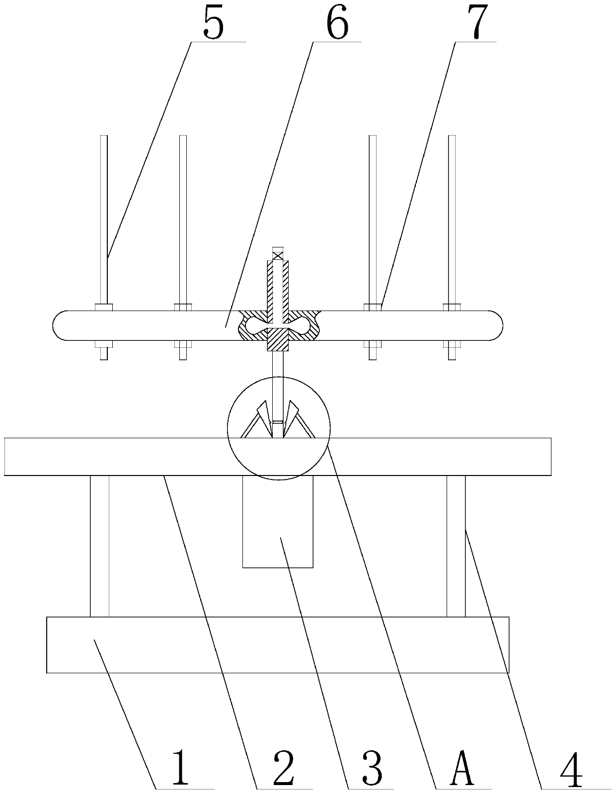
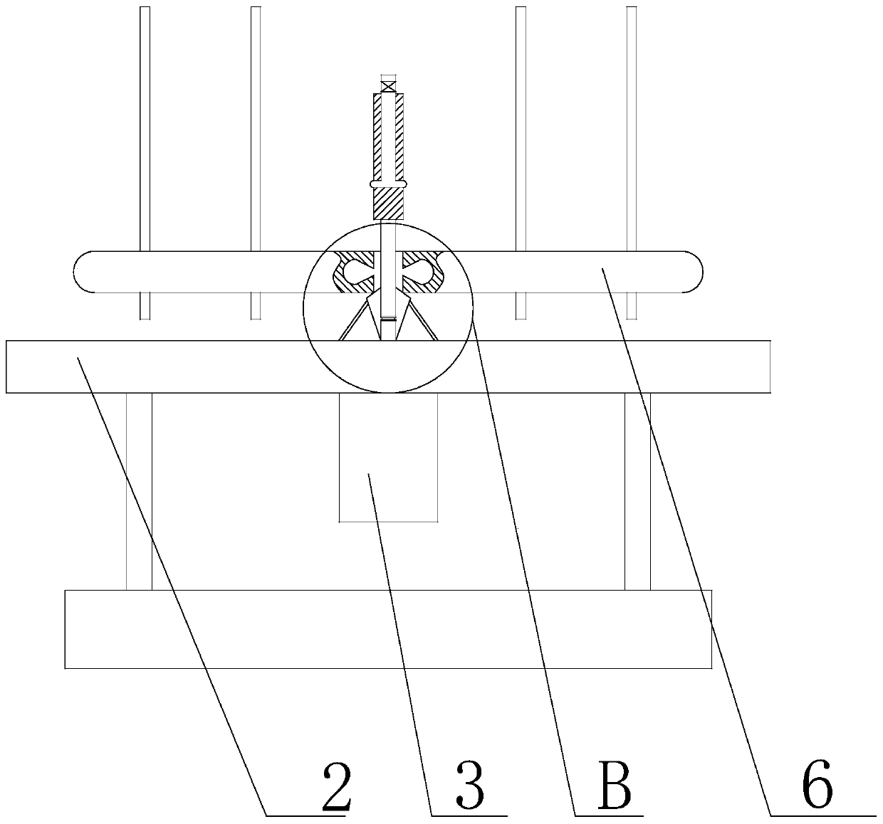
[0030] Such as Figure 1 to Figure 6 As shown, a cable retracting and unwinding device with fast braking function of the present invention includes a base 1, which is used for stably fixing on the construction ground, and supports rods 4 at the top four corners of the base 1. The top of the support rod 4 is provided with a support platform 2, and the bottom of the support platform 2 is provided with a drive mechanism 3, the drive mechanism 3 is located at the center of the support platform 2, the drive mechanism 3 is preferably a motor; the drive mechanism 3 includes The output shaft includes a first rotating rod 13 and a second rotating rod 21. The first rotating rod 13 penetrates the support platform 2 and is connected to the bottom of the second rotating rod 21. The first rotating rod 13 is connected, the driving mechanism 3 can drive the first rotating rod 13 and the second rotating rod 21 to rotate, and the diameter of the second rotating rod 21 is larger than the diameter...


PUM


Abstract

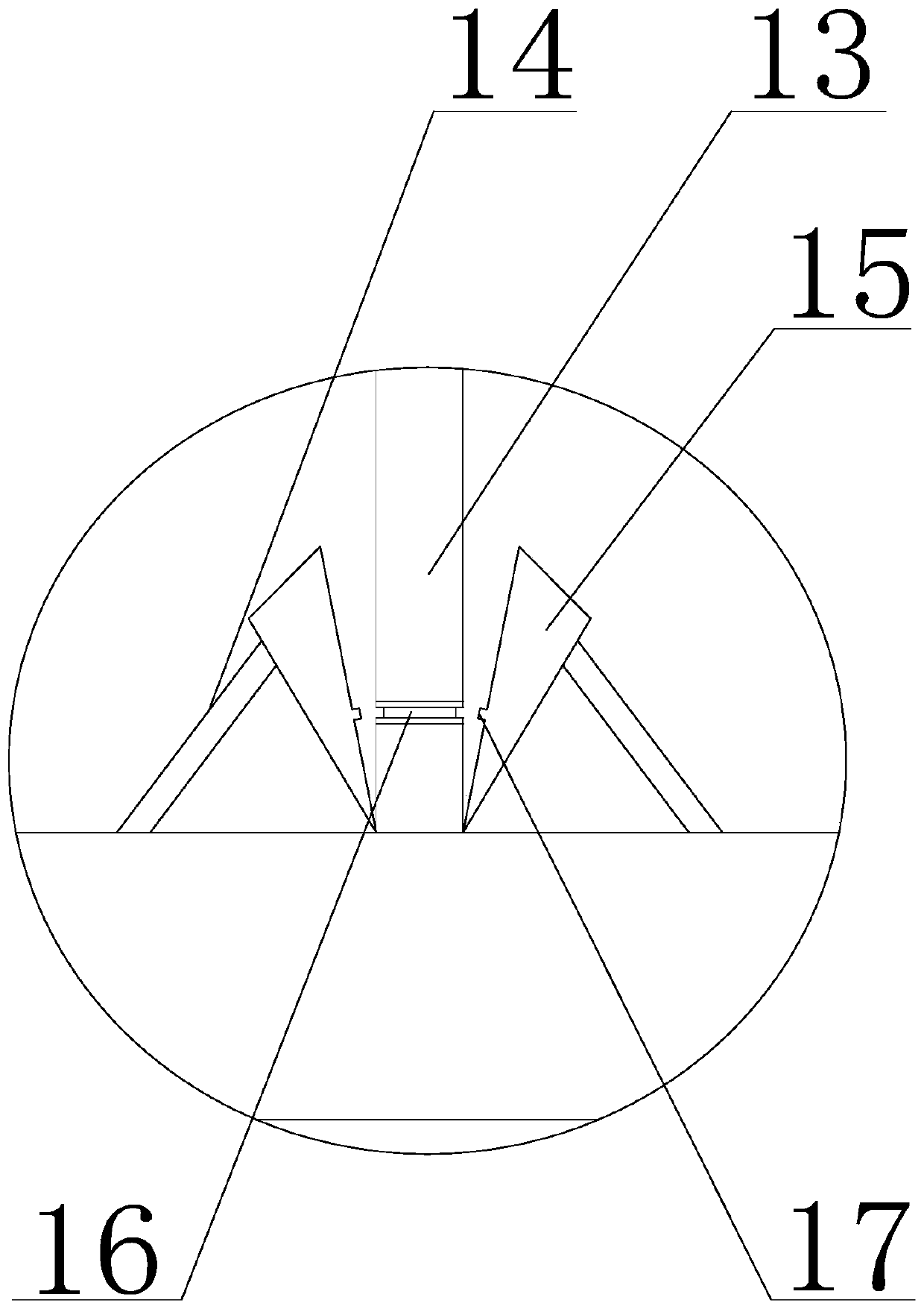
The invention discloses a cable winding and unwinding device with a quick braking function. The cable winding and unwinding device comprises a base of which the top is provided with support rods, anda support platform is arranged on the tops of the support rods; the bottom of the support platform is provided with a driving mechanism, and the driving mechanism comprises an output shaft which is provided with a wire spool; the wire spool is arranged on the output shaft in a sleeved manner, and can be moved along the outer wall of the output shaft; the output shaft is further provided with an airbag internally, and the wire spool is internally provided with a connecting cavity matched with the airbag; the top of the support platform is further provided with a plurality of deceleration blockshinged with the support platform, and the deceleration blocks are distributed on the outer side of the output shaft uniformly, and located below the wire spool; the top of the support platform is further provided with elastic parts of which the number is the same as the number of the deceleration blocks, and one end of each elastic part is connected with the support platform; the other end of theelastic part is connected with the corresponding deceleration block; when the elastic parts are not subjected to the action of external force, a clearance is formed between the deceleration blocks and the output shaft; and when the wire spool falls off from the output shaft, the deceleration blocks can be attached to the output shaft through the wire spool.

Description

Technical field [0001] The invention relates to the technical field of power tools, in particular to a cable retracting and unwinding device with a fast braking function. Background technique [0002] With the rapid development of the times, people’s living standards continue to improve, and the city’s electricity consumption is gradually increasing. Therefore, reducing power outages and improving the reliability and economy of the distribution network have become an urgent issue. The first choice to solve this problem is live work. It is not only one of the main measures necessary to improve the reliability of power supply, but also the specific performance of power supply companies to improve their core competitiveness. The use of bypass operations is becoming more and more widespread, but there are inevitably some problems in the operation process. [0003] The bypass cable is an imported flexible cable, which is expensive. It cannot be rubbed against the ground during deployme...

Claims


Application Information

Patent Timeline
Patent Type & Authority Patents(China)
IPC IPC(8): B65H75/38B65H75/44
Inventor 雷鹏黎平谢勇泉索玉鹏章有军
Owner PANZHIHUA POWER SUPPLY COMPANY STATE GRID SICHUAN ELECTRIC POWER
Learn More