
Auxiliary anode tool

An auxiliary anode and tooling technology, applied in the electrolysis process, electrolysis components, etc., can solve the problem that the auxiliary anode cannot be adjusted flexibly, and achieve the effect of convenient processing and molding, ensuring uniformity, and ensuring the coating layer.

Inactive Publication Date: 2019-05-31
HENAN PINGGAO ELECTRIC +2
View PDF7 Cites 0 Cited by
  • Summary
  • Abstract
  • Description
  • Claims
  • Application Information

AI Technical Summary

Problems solved by technology

[0005] The invention provides an auxiliary anode tooling to solve the problem that the auxiliary anode cannot be adjusted flexibly

Method used


Image

  • Auxiliary anode tool
  • Auxiliary anode tool
  • Auxiliary anode tool

Examples


Embodiment Construction

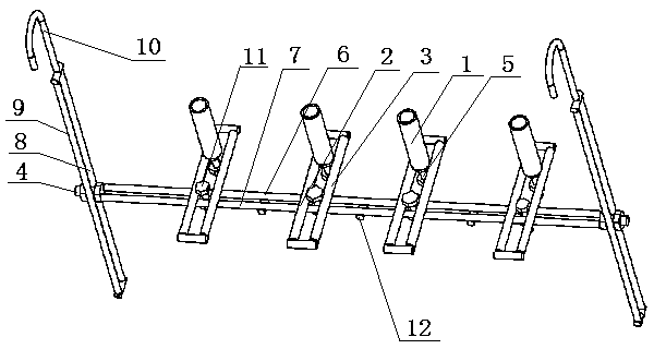
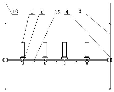
[0023] The auxiliary anode tooling of the present invention will be further described below in conjunction with the accompanying drawings.

[0024] Embodiments of the auxiliary anode tooling of the present invention, such as Figure 1~Figure 3 As shown, the auxiliary anode tooling includes a support platform made of stainless steel and left and right support frames. The support platform includes horizontal braces and vertical braces, and the auxiliary anode 1 is connected to the vertical braces.

[0025] Specifically, the structures of the left support frame and the right support frame are the same, such as figure 1 As shown, they are respectively arranged on the left and right sides of the auxiliary anode tooling, so take the left support frame as an example to illustrate the structure of the left and right support frames. The left support frame comprises the fifth support bar 8 and the sixth support bar 9 that are vertically parallel to each other, and the fifth support bar...


PUM


Abstract

The invention provides an auxiliary anode tool. The auxiliary anode tool comprises a supporting platform used for supporting and fixing auxiliary anodes and a left supporting platform and a right supporting frame used for supporting the supporting platform; the supporting platform is bridged between the left supporting frame and the right supporting frame, the supporting platform comprises transverse supports connected with the left support frame and the right support frame in a bridging mode, and at least one longitudinal support used for being connected with the auxiliary anodes is connectedto the transverse supports; the transverse supports are provided with transverse long holes allowing the transverse supports to freely move in the left-right direction, and the longitudinal supportsare provided with longitudinal long holes allowing the auxiliary anodes to freely move in the front-and-back direction of the transverse supports, the transverse long holes and the longitudinal long holes are arranged in a crossed manner; the positions of the auxiliary anodes can be flexibly adjusted according to the actual situation of to-be-plated parts through the transverse long holes and thelongitudinal long holes.

Description

technical field [0001] The invention relates to the technical field of electroplating, in particular to an auxiliary anode tooling. Background technique [0002] Most of the electroplating parts have complex structures and contain cavity structures. Restricted by the structure of the part, the cavity can only face up or down the plating tank, and the power line in the cavity cannot reach it, resulting in a greatly slowed down plating speed, making it difficult to guarantee a certain thickness of the coating, and even the phenomenon that the coating cannot be applied. [0003] The use of auxiliary anodes can make the parts to be plated that cannot be reached by the electric lines, such as deep recesses or the inside of the tube, have electric lines distribution, and it is easy to deposit the coating. [0004] At present, when electroplating is performed, the hook is usually welded to the frame body, and the position cannot be adjusted; in addition, the fixed position of the ...

Claims


Application Information

Patent Timeline
IPC IPC(8): C25D17/06C25D17/08
Inventor 杨晓涵王建华沈晓路亚娟王战辉雪金海王斌郭海涛马国臣娄金钢李梦娜李晓征刘翠翠温龙飞张央央王香玉余真真张明明
Owner HENAN PINGGAO ELECTRIC
Learn More