Improved textile waterproof performance detection device and detection method

A detection equipment and textile technology, applied in the field of improved textile waterproof performance detection equipment, can solve the problems of cumbersome operation, inability to realize gripper beating, poor practicability, etc., and achieve the effect of automatic operation

Pending Publication Date: 2019-05-31
江苏创标检测技术服务有限公司
View PDF1 Cites 4 Cited by
  • Summary
  • Abstract
  • Description
  • Claims
  • Application Information

AI Technical Summary

Problems solved by technology

[0003] The above-mentioned equipment can overcome the artificial variables in the existing test operation process, but it also has the following defects: the above-mentioned equipment can only realize the control of the sample angle and the water spraying operation, and cannot realize the beating of the holder, and the clamping without

Method used


Image

  • Improved textile waterproof performance detection device and detection method
  • Improved textile waterproof performance detection device and detection method
  • Improved textile waterproof performance detection device and detection method

Examples


Embodiment 1

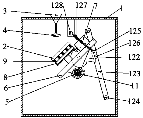
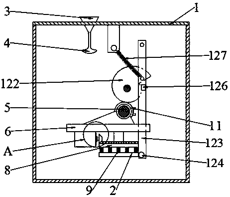
[0060] Such as Figure 1-4 As shown, in the improved textile waterproof performance testing equipment of Example 1, a funnel 3 is arranged in the through hole on the top surface of the box body 1, the bottom end of the funnel 3 is connected with a nozzle 4, and a rotating shaft is arranged between the opposite side walls of the box body 1 5. A base 6 is fixedly installed on the rotating shaft 5, and the surface of the base 6 is sequentially provided with a rotary driving member 7, a rotary supporting plate 8, an elastic connector 9 and the holder positioning substrate 2, and the connection between the box body 1 and the rotating shaft 5 A rotating shaft rotation drive member 11 is arranged between them, and a positioning substrate knocking mechanism 12 is arranged on the side of the rotating shaft 5 .

[0061] The positioning substrate knocking mechanism 12 includes a drive shaft 121, a special-shaped cam 122 fixedly pierced on the drive shaft 121, a swing arm 123 positioned a...

Embodiment 1

[0067] During embodiment 1 work, concrete steps are:

[0068] S1: Fix the holder with the sample fixedly connected to the holder positioning substrate 2;

[0069] S2: drive the rotating shaft to rotate the driving part 11 to adjust the inclination of the sample, and spray test water to the surface of the sample through the funnel 3 and the nozzle 4;

[0070] S3: drive the rotating shaft to rotate the driving member 11 to the level of the sample surface downward, drive the positioning substrate knocking mechanism 12 to knock the clamper positioning substrate 2;

[0071] S4: Drive the rotary drive member 7 to rotate the clamper positioning substrate 2 by 180° in the horizontal plane, and drive the positioning substrate knocking mechanism 12 to strike the clamper positioning substrate 2 again.

Embodiment 2

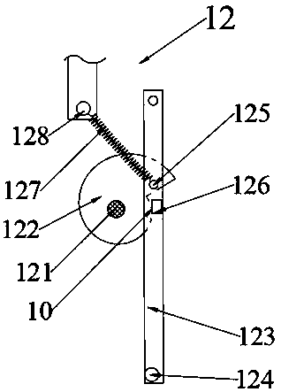
[0073] Such as Figure 5-7 As shown, embodiment 2 is based on embodiment 1, the difference is that the drive shaft 121 in the positioning substrate knocking mechanism 12 is the rotating shaft 5, the minimum distance between the involute and the center of the rotating shaft is the knocking contact point 10, and the knocking contact point 10 and the plane where the center of the rotating shaft 5 is parallel to the rotary pallet 8 and the holder positioning base plate 2 .

[0074] The return elastic member 127 is a compression spring, and the compression spring and the special-shaped cam 122 are located on both sides of the swing arm 123; the box body 1 is hingedly provided with a second elastic member positioning seat 129, and the pressing spring is arranged on the first elastic member positioning seat 125 and the second elastic positioning seat 129.

[0075] Special-shaped cams 122 are respectively pierced at both ends of the rotating shaft 5 , swing arms 123 are respectively ...


PUM


Abstract

The invention discloses an improved textile waterproof performance detection device. The device comprises a box body and a holder positioning substrate; a funnel is arranged in the through hole of thetop surface of the box body; the bottom end of the funnel is connected with a nozzle; a rotating shaft is disposed between the opposite side walls of the box body; the rotating shaft is fixedly provided with a base; a rotation driving component, a rotation support plate, an elastic connecting component and the holder positioning substrate are sequentially stacked on the surface of the base; a rotating shaft driving component is arranged between the box body and the rotating shaft; and the side surface of the rotating shaft is provided with a positioning substrate striking mechanism. The improved textile waterproof performance detection device is provided with the rotating shaft and the positioning substrate striking mechanism; the holder positioning substrate on the rotating shaft is usedfor positioning a fabric holder; the positioning substrate striking mechanism is used for striking the holder positioning substrate; the elastic connecting component can enhance the vibration of thestruck holder positioning substrate so as to shake off test water retained on the surface of the fabric. The invention also discloses a detection device-based textile waterproof performance detectionmethod.

Description

technical field [0001] The invention relates to the technical field of fabric detection devices, in particular to an improved textile waterproof performance detection equipment and detection method. Background technique [0002] The sample fixing equipment in the test instrument in GB / T4745-2012 "Testing and Evaluation of Waterproof Performance of Textiles" includes a sample holder and a base. In the test method, the sample needs to be clamped in the sample holder first. On the holder, the front of the sample textile is at an angle of 45° to the horizontal plane, and the spray water from the funnel above the textile falls to the front of the sample textile, and then the front of the sample textile needs to be turned down horizontally, and gently tap against a hard object Press the holder once, then rotate the holder 180° horizontally, tap the holder lightly, and finally evaluate the water level of the sample. The improved technical solution is as described in Chinese patent...

Claims


Application Information

Patent Timeline
IPC IPC(8): G01N15/08
Inventor 李世程张贤淼
Owner 江苏创标检测技术服务有限公司
Why Eureka
Try Eureka