Optical module shell structure

An optical module and casing technology, applied in the field of optical communication, can solve the problems of reducing the electromagnetic shielding effect of the optical module casing, and achieve the effects of good electromagnetic shielding ability, low cost, and smooth sliding of the pull ring

Pending Publication Date: 2019-05-31
LINKTEL TECH CO LTD
View PDF6 Cites 4 Cited by
  • Summary
  • Abstract
  • Description
  • Claims
  • Application Information

AI Technical Summary

Problems solved by technology

Conductive materials have excellent electromagnetic shielding effect, and the completely sealed metal casing has ideal shielding effect, but in practical applications, due to the "hot swap" function of the optical module, the shell needs to be designed with a pull ring structure, and at the same time, it is necessary to ensure The pull ring can slide back and forth easily, so there is usually a gap between the pull ring and the housing, which will greatly reduce the electromagnetic shielding effect of the optical module housing

Method used


Image

  • Optical module shell structure
  • Optical module shell structure
  • Optical module shell structure

Examples


Embodiment Construction

[0029] The following will clearly and completely describe the technical solutions in the embodiments of the present invention with reference to the accompanying drawings in the embodiments of the present invention. Obviously, the described embodiments are only some, not all, embodiments of the present invention. Based on the embodiments of the present invention, all other embodiments obtained by persons of ordinary skill in the art without making creative efforts belong to the protection scope of the present invention.

[0030] In describing the present invention, it is to be understood that the terms "center", "upper", "lower", "front", "rear", "left", "right", "vertical", "horizontal", The orientations or positional relationships indicated by "top", "bottom", "inner", "outer", etc. are based on the orientations or positional relationships shown in the drawings, and are only for the convenience of describing the present invention and simplifying the description, rather than in...


PUM


Abstract

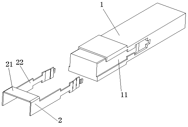
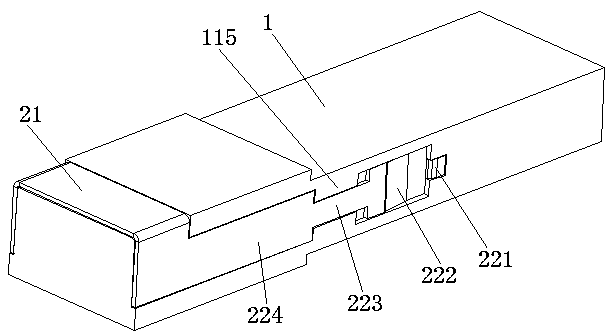
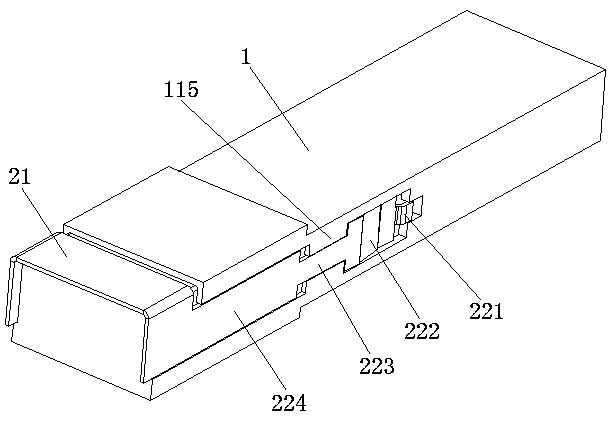
The invention belongs to the technical field of optical communication, and particularly relates to an optical module shell structure, comprising a shell body for packaging electronic parts of an optical module and a pull ring for mounting and detaching the optical module from a use device. The pull ring comprises a connecting plate and two slide pieces, two ends of the connecting plate are connected with the two slide pieces, and mounting slots for slidable mounting of the two slide pieces are respectively formed in two sides of the casing; each slide piece comprises an lock-unlock part for being matched with an elastic part in a mount cage to realize locking and unlocking, and the lock-unlock part is arranged at the end, away from the connecting plate, of the slide piece. According to theoptical module shell structure, the pull ring, which is assembled with the shell body, can slide forwards and backwards in the mounting slots at two sides of the optical module shell body when beingpulled, the lock-unlock parts at the tail ends are then pulled to be matched with the elastic parts in the mount cage so as to realize locking and unlocking, and thus, the optical module can be mounted on or detached from the use device.

Description

technical field [0001] The invention belongs to the technical field of optical communication, and in particular relates to an optical module shell structure. Background technique [0002] According to the provisions of the optical module industry agreement MSA, the optical module has the feature of "hot swapping", that is, the optical module can be connected or disconnected from the device without turning off the power of the device. To ensure that the optical module can be reliably hot-swapped, it is generally required that the optical module is equipped with a locking and unlocking device. When the optical module is inserted into the installation cage of the equipment, it is locked by the contact between the structural steps on both sides of the optical module and the locking plate of the cage, so that the module is fixed in the cage to work. When the module needs to be pulled out, the spring locking plate on the cage It is lifted by the unlocking part of the pull ring of...

Claims


Application Information

Patent Timeline
Patent Type & Authority Applications(China)
IPC IPC(8): G02B6/42
Inventor 彭峰李林科吴天书杨现文张健
Owner LINKTEL TECH CO LTD
Why Eureka
Try Eureka