Magnet mold pressing device capable of accelerating cooling and facilitating material taking

An accelerated cooling and easy-to-take technology, applied in the direction of visible signal devices, signal devices, measuring devices, etc., can solve the problems of lack of temperature detection warning structure, lack of rapid cooling structure, lack of easy-to-install structure, etc., to speed up the cooling speed , Easy to take the mold, speed up the effect of heat dissipation

Active Publication Date: 2022-07-05
南通和力磁材有限公司
View PDF14 Cites 0 Cited by
  • Summary
  • Abstract
  • Description
  • Claims
  • Application Information

AI Technical Summary

Problems solved by technology

[0008] The object of the present invention is to provide a convenient magnet molding device for accelerated cooling, to solve the problems in the above-mentioned background technology, such as the lack of a convenient structure for taking molds, the lack of convenient Problems of installation structure, lack of rapid cooling structure, lack of temperature detection warning structure

Method used


Image

  • Magnet mold pressing device capable of accelerating cooling and facilitating material taking
  • Magnet mold pressing device capable of accelerating cooling and facilitating material taking
  • Magnet mold pressing device capable of accelerating cooling and facilitating material taking

Examples


Embodiment 2

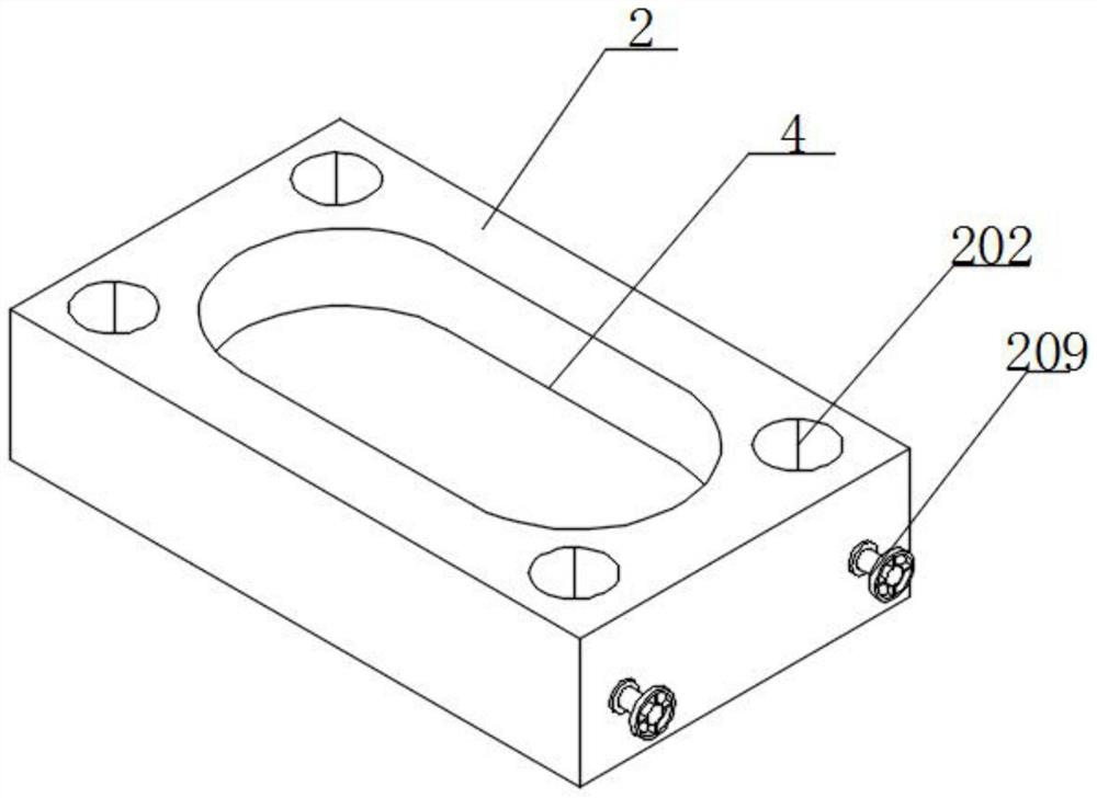
[0044] Example 2: see figure 2 and Figure 4 , an embodiment provided by the present invention: a convenient reclaiming magnet molding device for accelerated cooling, the top of the bottom mold 2 is provided with a mounting hole 202, and the inner wall of the mounting hole 202 is mounted with a plurality of inclined plates 203 through a rotating shaft, and the inclined plate 203 is installed on the inner wall of the bottom mold 2 A first spring 204 is installed on the outer wall of the plate 203, and one end of the first spring 204 is connected to the inner wall of the installation hole 202. The outer wall of the inclined plate 203 is installed with a retractable cable 207, and the outer wall of the retractable cable 207 is sleeved with a clamping block 201 , the inner wall of the installation hole 202 is installed with the rewinding shaft 205, and the retractable cable 207 is wound on the outer wall of the reeling shaft 205, one end of the inclined plate 203 is installed wit...

Embodiment 3

[0045] Example 3: see Figure 5 and Image 6 , an embodiment provided by the present invention: a convenient reclaiming magnet molding device for accelerated cooling, the outer wall of the die 4 is installed with a plurality of sliding grooves 401, the outer wall of the sliding groove 401 is installed with a cooling fin 402, and the outer wall of the cooling fin 402 is installed A heat dissipation pipe 403 is installed around the outer wall, and one end of the heat dissipation pipe 403 extends into the interior of the water tank 5. Fans 404 are installed on both inner walls of the bottom mold 2, and a waterproof casing 501 is installed on the inner wall of the water tank 5. A water pump 502 is installed on the bottom wall, a water inlet pipe is installed at the input end of the water pump 502, and one end of the water inlet pipe extends into the interior of the water tank 5, the output end of the water pump 502 is installed with a water outlet pipe, and one end of the water ou...

Embodiment 4

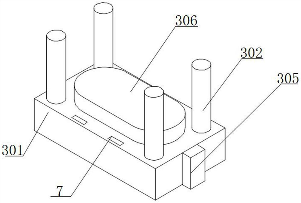
[0046] Example 4: see Figure 7 and Figure 8 , an embodiment provided by the present invention: a convenient reclaiming magnet molding device for accelerated cooling, a support plate 601 is installed on the top of the electric telescopic rod 6, and the top of the support plate 601 is connected with the bottom of the bottom mold 2, the bottom mold A drive motor 604 is installed on the inner wall of A vibration plate 602 is installed on the shaft, a return spring 603 is installed on the outer wall of the vibration plate 602, and one end of the return spring 603 is connected with the bottom of the bottom mold 2. When the mold is taken, the drive motor 604 is activated, and the drive motor 604 drives the rotation rod 605 to rotate , the rotating rod 605 drives the impact rod 606 to rotate, the impact rod 606 drives the impact ball 607 to rotate, the impact ball 607 rotates and hits the vibration plate 602, the vibration plate 602 vibrates after receiving the impact, and the vibr...


PUM


Abstract

The magnet mold pressing device comprises a rack, a bottom mold, a hydraulic rod and a water tank, the bottom mold is installed on the outer wall of the rack, the hydraulic rod is installed at the top of the rack, the bottom of the hydraulic rod extends out of the bottom of the rack, the water tank is installed on the back face of the bottom mold, and a female mold is arranged at the top of the bottom mold; and an electric telescopic rod is mounted on the inner bottom wall of the bottom die. By installing the vibration plate and the impact ball, die taking can be conveniently conducted, the driving motor drives the rotating rod to rotate, the rotating rod drives the impact rod to rotate, the impact rod drives the impact ball to rotate, and the impact ball rotates to impact the vibration plate, so that vibration is received between the female die and the magnet, the magnet and the female die are separated, and bonding is prevented; and then the electric telescopic rod is started, the electric telescopic rod drives the supporting plate to rise, the supporting plate drives the female die to stretch out of the bottom die, and the function of conveniently taking the die is achieved.

Description

technical field [0001] The invention relates to the technical field of magnet manufacturing, in particular to a convenient material-receiving magnet molding device for accelerated cooling. Background technique [0002] Magnets refer to substances or materials that can generate magnetic fields. Permanent magnets are made of steel or other materials. Steel or other materials can become permanent magnets because they are properly treated and processed. In the best state, the coercivity is the largest. To optimize the internal inhomogeneity of the steel, proper heat treatment or machining is necessary. After the carbon steel is quenched from high temperature, the unevenness grows rapidly and becomes a permanent magnet material. [0003] The defects of the existing magnet molds are: [0004] 1. The reference document CN106493360A discloses a pressing mold for NdFeB magnets, and the protection claim "it includes: two first side plates arranged along the magnetic field orientati...

Claims


Application Information

Patent Timeline
Patent Type & Authority Applications(China)
IPC IPC(8): H01F41/02B22F3/03B22F3/00H05K7/20G08B5/38G01K1/02
CPCH01F41/0266H01F41/02B22F3/03B22F3/005B22F3/003H05K7/20136H05K7/20218G01K1/02G08B5/38
Inventor 王昭钰曹建军
Owner 南通和力磁材有限公司
Why Eureka
Try Eureka