
Stirrup feeding device for welding steel reinforcement cages

A technology of feeding device and reinforcing cage, applied in the field of stirrup feeding device, can solve the problems of high labor cost and low work efficiency, etc.

Inactive Publication Date: 2019-06-04
CHINA MINSHENG ZHUYOU
View PDF8 Cites 4 Cited by
  • Summary
  • Abstract
  • Description
  • Claims
  • Application Information

AI Technical Summary

Problems solved by technology

[0004] The technical problem to be solved by the present invention is to provide a stirrup feeding device for steel cage welding to solve the existing problems of relying on manual feeding of good stirrups on the hoop bending machine to the steel cage welding equipment in the prior art. Technical problems of low work efficiency and high labor costs

Method used


Image

  • Stirrup feeding device for welding steel reinforcement cages
  • Stirrup feeding device for welding steel reinforcement cages
  • Stirrup feeding device for welding steel reinforcement cages

Examples


Embodiment 1

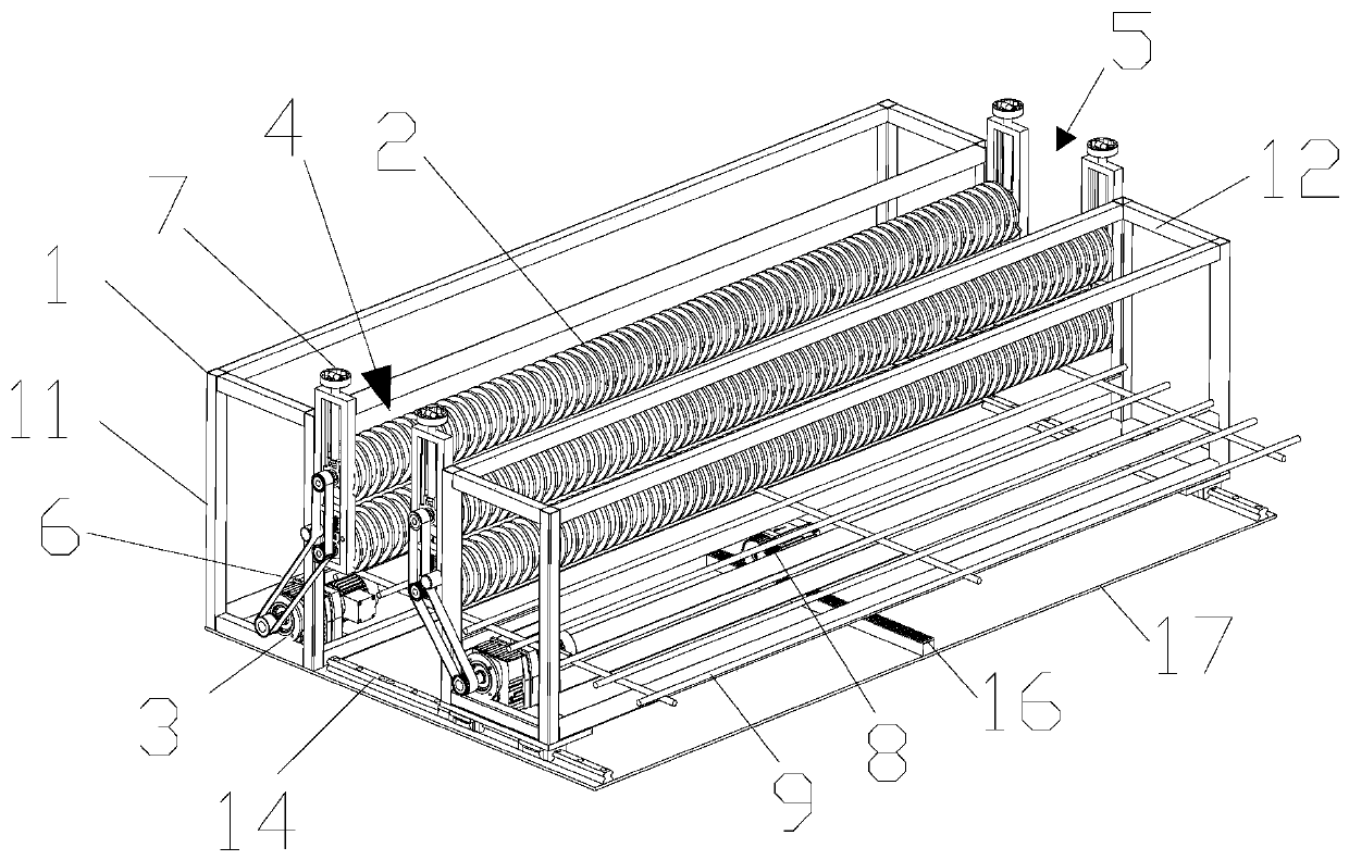
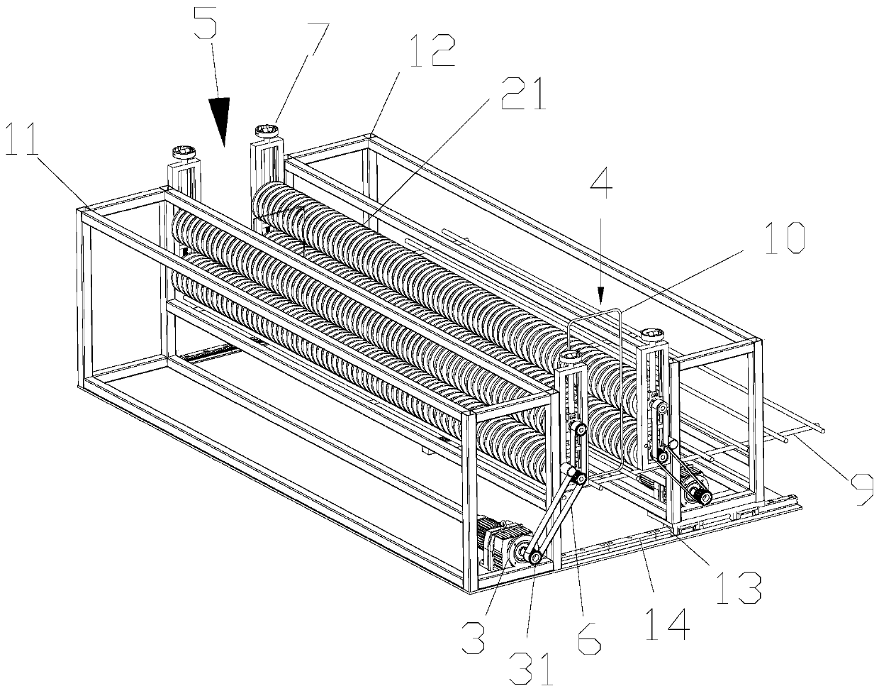
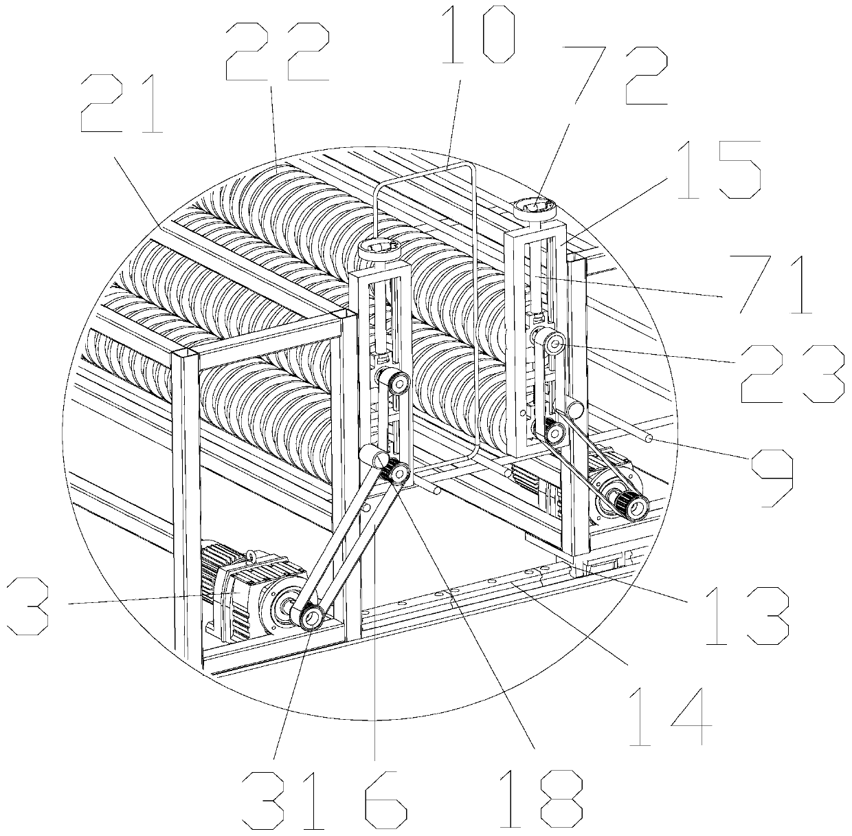
[0027] Reference figure 1 , The stirrup feeding device for steel cage welding in this embodiment includes a base 1, a screw conveying device 2 and a driving device 3. In this embodiment, the base 1 is a frame formed by welding a plurality of metal pipes, and gaps are respectively provided at both ends of the base 1 to form the inlet 4 and the outlet 5 of the stirrup. In order to enhance the overall stability, the bottom side of the base 1 in this embodiment is also provided with a bottom plate 17 fixedly connected with the metal pipe. The two ends of the screw conveying device 2 are respectively fixed on the two ends of the feed port 4 and the discharge port 5 on the base 1 . In this solution, the setting direction of the feed port and the discharge port is opposite, which does not affect the realization of the stirrup conveying function. The driving device 3 is fixed on the bottom plate 17 at one end of the base 1 . In this embodiment, the driving device 3 is a motor, whic...


PUM


Abstract

The invention discloses a stirrup feeding device for welding steel reinforcement cages. The stirrup feeding device includes a base, a screw conveying device and a driving device, the screw conveying device includes two groups of screw rods which are oppositely arranged and have a certain interval in the middle, spiral clamping grooves are formed in the surfaces of the screw rods, rotating shafts are arranged at the two ends of the screw rods, and the rotating shafts are fixed to the base; and the driving device is fixed to the base, and the driving device drives the rotating shafts to rotate.The stirrup feeding device for welding the steel reinforcement cages can be used as a stirrup material caching and equidistant conveying device, the spiral clamping grooves of screw conveying deviceson the left side and the right side are fully used for restraining stirrups, the driving device drives the stirrups to move in a straight line along a spiral line when driving the screw conveyors to rotate, and thus transport and feeding of the stirrups are achieved.

Description

technical field [0001] The invention belongs to the technical field of steel bar processing in construction, in particular, the invention relates to a stirrup feeding device for welding steel bar cages. Background technique [0002] A reinforcement cage consisting of longitudinal bars and stirrups needs to be placed in the beam or column. For the steel cages of cast-in-place beams or columns, manual tying was used on site in the past. This operation has low efficiency, high labor costs and potential safety hazards. After the development of mechanization, cast-in-place beams or columns and prefabricated beams or columns are now mostly completed by machine welding in factories. The raw materials of longitudinal bars and stirrups need to be processed separately, and then the processed longitudinal bars and stirrups are transported to welding equipment respectively, and the stirrups are welded to the longitudinal bars by laser welding and other methods. [0003] In the prior a...

Claims


Application Information

Patent Timeline
Patent Type & Authority Applications(China)
IPC IPC(8): B21F23/00B21F27/20B21F15/08
Inventor 黄岸薛英杰
Owner CHINA MINSHENG ZHUYOU
Learn More