Protective layer applicator for steel structures

A technology of protective layer and steel structure, applied in the direction of building structure, construction, etc., can solve the problems of waste of protective layer coating liquid and uneven coating.

Active Publication Date: 2020-12-11
中博建设工程集团有限公司
View PDF6 Cites 0 Cited by
  • Summary
  • Abstract
  • Description
  • Claims
  • Application Information

AI Technical Summary

Problems solved by technology

[0003] However, when the traditional steel structure is protected, a smear brush is used to smear the protective liquid on the side wall of the steel structure, or the protective liquid is sprayed on the steel structure through the nozzle, which causes uneven application and waste of the protective layer smear liquid during use.

Method used


Image

  • Protective layer applicator for steel structures
  • Protective layer applicator for steel structures
  • Protective layer applicator for steel structures

Examples


Embodiment 1

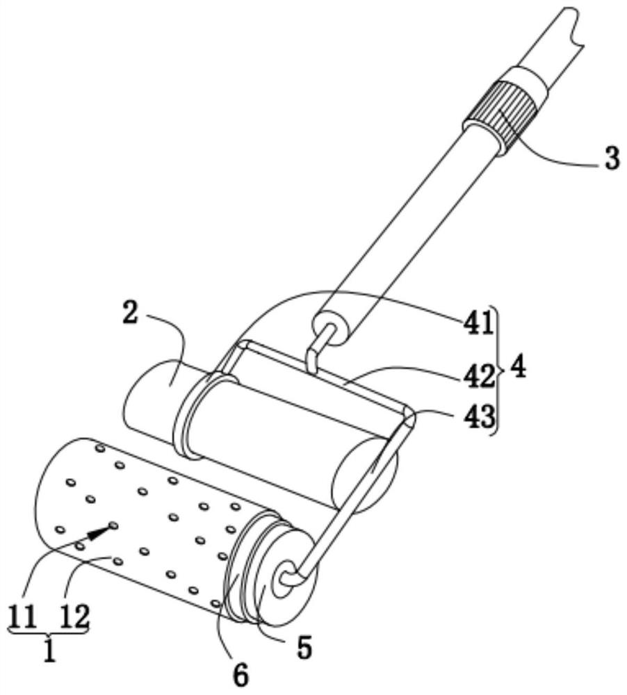
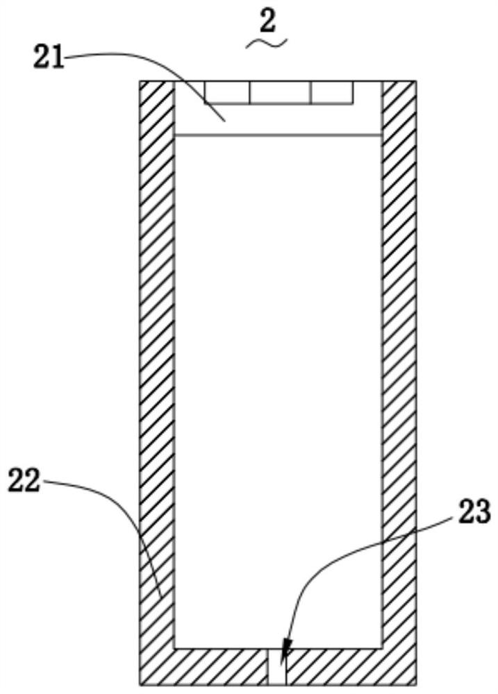
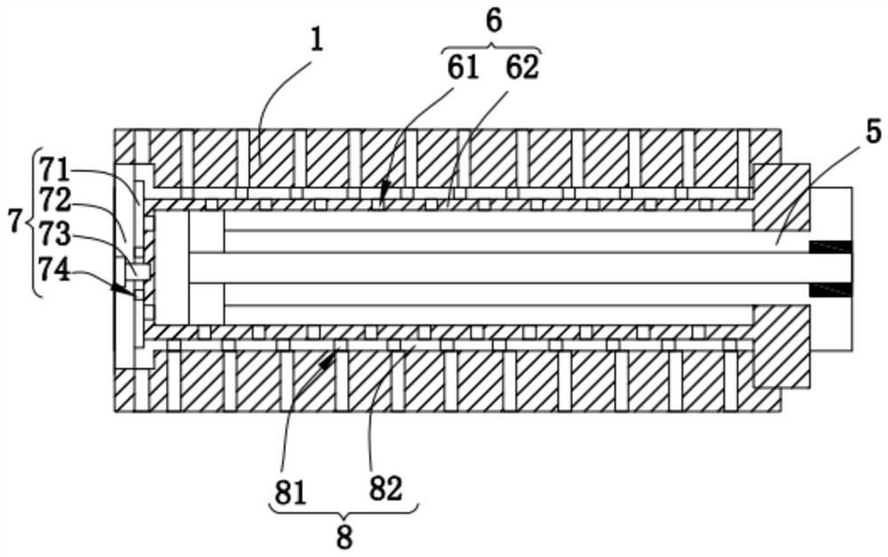
[0027] Please refer to figure 1 , figure 2 , image 3 , Figure 4 and Figure 5 ,in, figure 1 A schematic structural view of a preferred embodiment of the protective layer coating device for steel structures provided by the present invention; figure 2 for figure 1 A schematic diagram of the internal structure of the storage structure shown; image 3 for figure 1 A schematic diagram of the connection structure between the first smear structure and the second smear structure shown; Figure 4 for image 3 Structural schematic diagram of the drive structure shown; Figure 5 It is a structural schematic diagram of the supporting structure of Embodiment 1 of the protective layer coating device for steel structures provided by the present invention. A protective layer application device for a steel structure, comprising: a support structure 3; a fixed structure 4, the fixed structure 4 is fixed to the support structure 3; a storage structure 2, the storage structure 2 is ...

Embodiment 2

[0034] Please refer to figure 1 , figure 2 , image 3 , Figure 4 and Figure 6 ,in, figure 1 A schematic structural view of a preferred embodiment of the protective layer coating device for steel structures provided by the present invention; figure 2 for figure 1 A schematic diagram of the internal structure of the storage structure shown; image 3 for figure 1 A schematic diagram of the connection structure between the first smear structure and the second smear structure shown; Figure 4 for image 3 Structural schematic diagram of the drive structure shown; Figure 6 It is a structural schematic diagram of the supporting structure of the second embodiment of the protective layer application device for steel structures provided by the present invention. A protective layer application device for a steel structure, comprising: a support structure 3; a fixed structure 4, the fixed structure 4 is fixed to the support structure 3; a storage structure 2, the storage st...


PUM


Abstract

The invention provides a protective layer smearing device for a steel structure. The protective layer smearing device for the steel structure comprises a supporting structure, a fixing structure, a storage structure, a driving structure, an adjusting structure, a limiting structure and a first smearing structure; the adjusting structure comprises a plurality of third flow-guiding holes and an adjusting cylinder, the adjusting cylinder communicates with the storage structure through the driving structure, and the third flow-guiding holes are formed in the side wall of the adjusting cylinder; the limiting structure comprises a plurality of fourth flow-guiding holes and a sleeve, and the third flow-guiding holes in the adjusting cylinder are in one-to-one correspondence with the fourth flow-guiding holes in the sleeve; and the first smearing structure comprises a smearing roller and first smearing holes, and the fourth flow-guiding holes in the sleeve are in one-to-one correspondence withthe first smearing holes in the smearing roller. The protective layer smearing device for the steel structure is good in smearing effect and high in protective liquid utilization efficiency.

Description

technical field [0001] The invention relates to the technical field of construction, in particular to a protective layer coating device for steel structures. Background technique [0002] Steel structure is a structure composed of steel materials, which is one of the main types of building structures. The structure is mainly composed of steel beams, steel columns, steel trusses and other components made of section steel and steel plates. Welding seam, bolt or rivet connection, because of its light weight and easy construction, is widely used in large factories, venues, super high-rise and other fields. The setting of the protective layer of the steel structure effectively improves the service life of the steel structure. The use of the advanced protective layer application device improves the work efficiency of steel structure maintenance and protection. [0003] However, when traditional steel structures are protected, a smear brush is used to smear protective liquid on th...

Claims


Application Information

Patent Timeline
Patent Type & Authority Patents(China)
IPC IPC(8): E04F21/06
Inventor 孙中玲秦祖才赵玲燕贾桂莲
Owner 中博建设工程集团有限公司
Why Eureka
Try Eureka