
Parking brake device for rail transit vehicle and manual mitigation method thereof

A rail transit vehicle, parking braking technology, applied in the direction of brake actuators, gear transmission mechanisms, mechanical equipment, etc., can solve the problems of many parts, high processing and assembly requirements, complex structure, etc., and achieve high reliability and durability High performance, convenient engineering operation, simple and compact structure

Pending Publication Date: 2019-06-04
CRRC CHANGZHOU TECH MARK IND CO LTD +1
View PDF4 Cites 0 Cited by
  • Summary
  • Abstract
  • Description
  • Claims
  • Application Information

AI Technical Summary

Problems solved by technology

[0003] U.S. Patent US2003154854A1 discloses a spring brake cylinder and an emergency release device, which is a typical parking brake device. Various tasks are completed by screwing complex components, etc. The parking brake device operates stably and has high reliability , but the structure is particularly complex, there are many parts, and the processing accuracy is extremely high, and the assembly, disassembly and maintenance are more cumbersome
[0004] The structure of the parking brake device involved in the Chinese patents CN202272010U and CN102795240A is similar to the technical solution in the US patent US2003154854A1, but there are also problems such as too complicated structure, many parts, and high processing and assembly requirements.
The vertical movement of the push block is extremely limited due to space constraints, and it is difficult to transfer the movement to the wedge pin well
It is difficult to realize engineering application

Method used


Image

  • Parking brake device for rail transit vehicle and manual mitigation method thereof
  • Parking brake device for rail transit vehicle and manual mitigation method thereof
  • Parking brake device for rail transit vehicle and manual mitigation method thereof

Examples


Embodiment 1

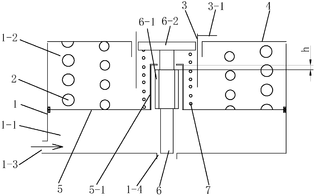
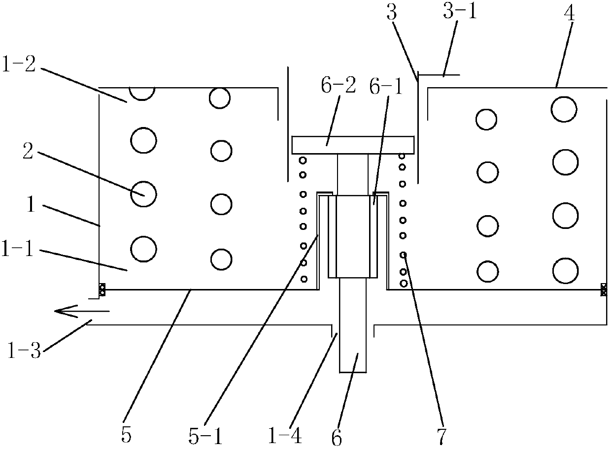
[0037] See Figure 1 to Figure 14 , this embodiment includes a cylinder body 1, a cylinder head 4, a parking piston 5 and a brake lever 6, the parking piston 5 divides the cylinder cavity into a first cavity 1-1 below and a second cavity 1-2 above, Corresponding to the first chamber 1-1, the cylinder body 1 is provided with an air inlet 1-3 and a brake lever outlet 1-4, and a parking spring 2 is arranged in the second chamber 1-2, and the upper end of the parking spring 2 is in contact with the cylinder. Cover 4 is offset, and the lower end is offset with parking piston 5 .

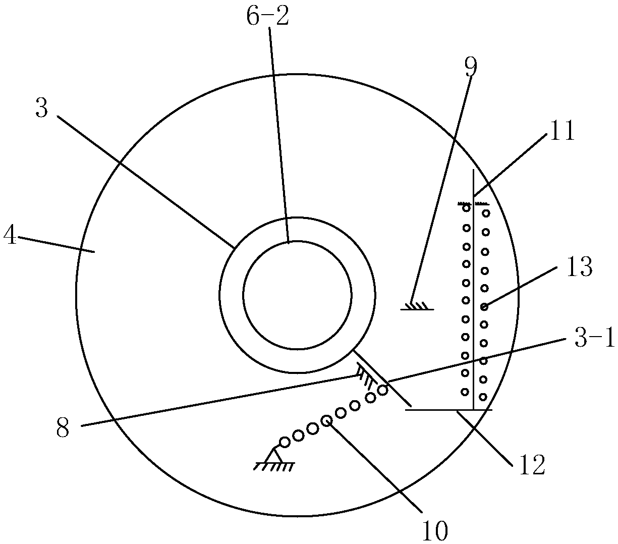
[0038] The center of the parking piston 5 is provided with an upwardly protruding limit cover 5-1, the middle part of the brake lever 6 is provided with a spline body 6-1, and the teeth of the spline body 6-1 of the brake lever 6 There are at least 4 teeth. In the accompanying drawings, the spline body 6-1 of the brake lever 6 has 6 teeth, and the tooth ends are arc-shaped. The top of the limit cover 5-...

Embodiment 2

[0046] Figure 15 and Figure 16 As shown, the spline body 6-1 of the brake lever 6 in this embodiment is provided with 12 teeth, and the top of the piston limit cover 5-1 is provided with 12 teeth that match the spline body 6-1 of the brake lever 6. A spline groove 5-1a. See embodiment 1 for others.


PUM


Abstract

The invention discloses a parking brake device for a rail transit vehicle. The parking brake device for the rail transit vehicle includes a cylinder block, a parking piston, a brake lever, a cylinderhead, and a parking spring, wherein the center of the parking piston is provided with a limit cover protruding upwardly; a spline body is arranged on the middle portion of the brake lever; a spline groove is arranged on the top portion of the limit cover; the spline body of the brake lever is in dynamic fit with the limit cover; the upper end of the brake lever penetrates through the spline grooveand extends into a second cavity; a guide seat is fixed at the upper end of the brake lever; the limit cover is sleeved with a brake lever spring; the brake lever is provided with a first rotation position for staggering the spline body and the spline groove of the limit cover, and a second rotating position for matching the spline body with the spline groove of the limit cover; the cylinder headis provided with a rotating disc, a rotating disc spring, a first stop member corresponding to the first rotating position of the brake lever, and a second stop member corresponding to the second rotating position of the brake lever; the rotating disc is connected to the guide seat; and the rotating disc is provided with a radial shifting lever. By means of the parking brake device for the rail transit vehicle, pneumatic mitigation, parking brake and manual mitigation are achieved. The parking brake device for the rail transit vehicle has the advantages of less parts, simple and compact structure, light weight and low manufacturing cost, thereby achieving engineering application conveniently.

Description

technical field [0001] The invention relates to a parking brake device for a rail transit vehicle and a manual release method thereof. Background technique [0002] The parking brake device is mainly used for the parking needs of rail transit vehicles under windless conditions (such as parking in garages at night, parking on faulty vehicle lines, etc.). Parking brake devices mostly use high-pressure springs for energy storage. When the parking brake is not required, the compressed gas is charged into the parking brake cylinder to overcome the spring force and store energy; when the parking brake is required, the compressed air in the parking brake cylinder is discharged, and the energy storage spring releases energy, thereby applying the parking brake move. The parking brake device has the functions of parking brake, inflation release, and manual release according to different work requirements. Parking brake and charge relief are available with compressed air: Parking br...

Claims


Application Information

Patent Timeline
IPC IPC(8): F16D65/14F16D121/04F16D121/06F16D121/16
Inventor 苟青炳张宇宸吴波金璟徐昊尹仁华沈冬卫汪冬冬
Owner CRRC CHANGZHOU TECH MARK IND CO LTD
Features
  • Generate Ideas
  • Intellectual Property
  • Life Sciences
  • Materials
  • Tech Scout
  • Unparalleled Data Quality
  • Higher Quality Content
  • 60% Fewer Hallucinations
Learn More