Hydraulic drainage valve

A drainage valve and hydraulic technology, which is applied in the direction of sliding valves, valve details, valve devices, etc., can solve the problems of laborious driving and control of drainage valves, slow response, etc., and achieve the effect of simple structure, low hydraulic pressure and high water pressure

Pending Publication Date: 2019-06-04
贵州兴建科技有限公司
View PDF0 Cites 0 Cited by
  • Summary
  • Abstract
  • Description
  • Claims
  • Application Information

AI Technical Summary

Problems solved by technology

[0002] At present, due to the huge pressure of water on the drain valve of a large pool, the traditional water valve needs a lot of forc

Method used


Image

  • Hydraulic drainage valve
  • Hydraulic drainage valve
  • Hydraulic drainage valve

Examples


Embodiment Construction

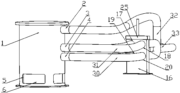
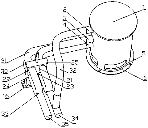
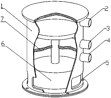
[0025] exist figure 1 Among them, the outer wall of the cavity (1) is provided with an exhaust port (2), an upper port (3), a lower port (3) and four water valve inlet holes (5), and the piston (6) is installed in the cavity ( 1) Inside. One port of the exhaust pipe body (32) is connected with the exhaust interface (2), and the two nozzles at the other end of the exhaust pipe body (32) are connected with the interface on the other side of the switching valve slot (16). One end of the pipe body M (31) is connected to the upper port (3), and the two nozzles at the other end of the pipe body M (31) are connected to the port A (17) and port B (18) on the switch valve slot (16). connected. One end of the pipe body L (30) is connected to the lower interface (4), and the two nozzles at the other end of the pipe body L (30) are connected to the interface C (19) and the interface D (20) on the switch valve slot (16). connected. The water inlet pipe body (33) is connected with the i...


PUM


Abstract

The invention discloses a hydraulic drainage valve capable of being driven and controlled hydraulically through relatively small pressure. The hydraulic drainage valve is formed by installing a cavity, a piston, a pipe body M, a pipe body L, an exhaust pipe body, a water inlet pipe body, a switch valve inserting groove and a switch valve. When the hydraulic drainage valve needs to be opened, a switch handle is lifted to enable the piston to move upwards, a water valve water inlet hole is connected with a water tank water outlet port, so that a water valve is opened to realize drainage; when the hydraulic drainage valve needs to be closed, the switch handle is pushed downwards to enable the piston to move downwards, when the piston moves to the bottom end, the water valve water inlet hole is disconnected with the water tank water outlet port, so that the water valve is closed.

Description

technical field [0001] The invention relates to a drain valve device that can be driven and controlled by hydraulic pressure, especially a drain valve that can be driven and controlled by low pressure. Background technique [0002] At present, the drain valve of a large pool is subjected to huge pressure of water, so that the traditional water valve needs a lot of force to open or close the water valve when draining, making the drive control of the drain valve laborious and slow in response. Contents of the invention [0003] In order to overcome the disadvantage that the traditional drain valve is difficult to open and close after being subjected to high water pressure, the present invention provides a hydraulic drain valve, which can control the opening and closing of the drain valve under the hydraulic drive of a small pressure. [0004] The technical solution adopted by the present invention to solve the technical problem is: install the cavity of the hydraulic drain v...

Claims


Application Information

Patent Timeline
IPC IPC(8): F16K3/24F16K31/124F16K27/04
Inventor 向金位邓凡吕林田双曾毅
Owner 贵州兴建科技有限公司
Why Eureka
Try Eureka