Continuous-zoom small-field high-speed panorama infrared optical system

An infrared optical system and a small field of view technology, applied in the field of infrared optical systems, can solve problems such as image blurring, and achieve the effect of increasing the degree of freedom, ensuring imaging quality, and clearing imaging images.

Active Publication Date: 2019-06-04
LUOYANG INST OF ELECTRO OPTICAL EQUIP OF AVIC
View PDF6 Cites 0 Cited by
  • Summary
  • Abstract
  • Description
  • Claims
  • Application Information

AI Technical Summary

Problems solved by technology

[0002] Compared with the linear imaging system, the continuous motion imaging of the area array imaging system is easier to implement key monitoring and tracking of key areas during variable-speed scanning. The difficulty in its application lies in the relative motion between the focal plane and the scene within the detector integration time. thus blurring the image

Method used


Image

  • Continuous-zoom small-field high-speed panorama infrared optical system
  • Continuous-zoom small-field high-speed panorama infrared optical system
  • Continuous-zoom small-field high-speed panorama infrared optical system

Examples


Embodiment Construction

[0024] Now in conjunction with embodiment, accompanying drawing, the present invention will be further described:

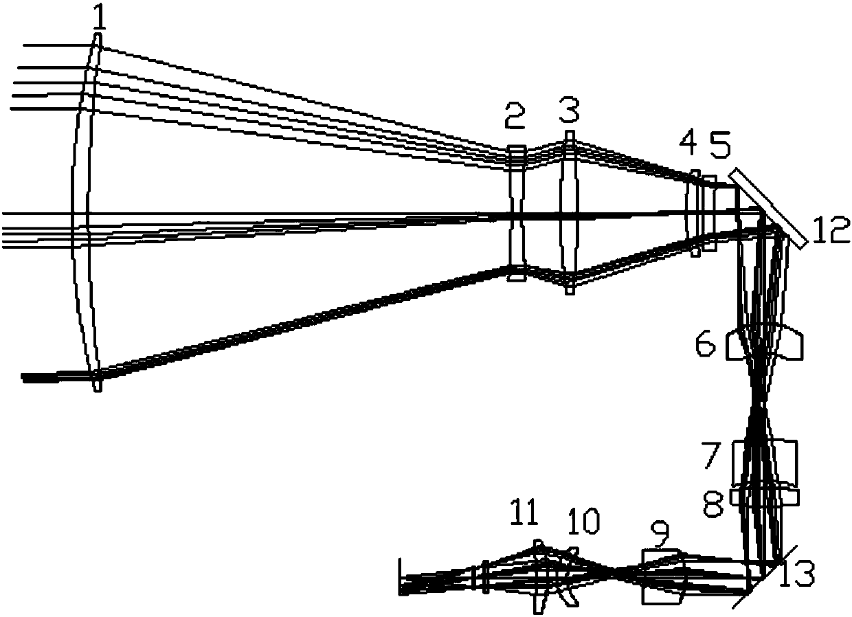
[0025] like figure 1 , Table 1 shows the structure diagram and optical principle diagram of the best embodiment of a kind of continuously zooming small field of view high-speed surrounding infrared optical system designed by the present invention. The design band of the infrared system is 3.7-4.8μm, and the parameters of the cooling detector are: the number of pixels is 640×512, and the F / # is 4.

[0026] The optical system parameter table is:

[0027]

[0028]

[0029]

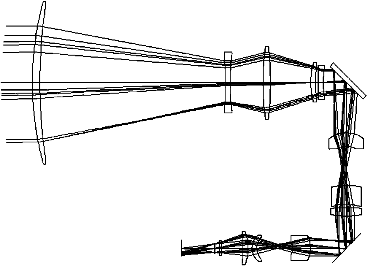
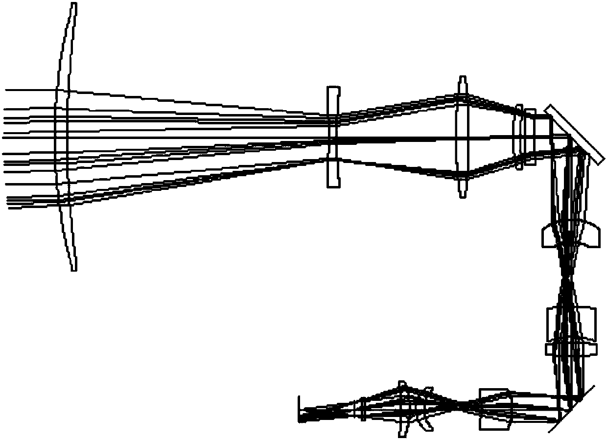
[0030] Among them: the zoom position parameter Z is shown in Table 2.

[0031] Table 2 Continuous zoom position parameter list

[0032] zoom position

Focal length 366mm

Focal length 275mm

Focal length 137.5mm

Focal length 22.4mm

Z1

115.99.

112.14

96.13

12.57

Z2

10.5

19.71

43.87

138.61

Z3

29.69

24.33

16.18

...


PUM


Abstract

The invention relates to a continuous-zoom small-field high-speed panorama infrared optical system. A 16-power continuous-zoom optical system is designed through theoretical calculation and analysis.A scanning swinging mirror is added to a parallel optical path in a small-field optical structure, the scanning swinging mirror swings back for a certain angle to compensate the field angle for movement of an imaging system, the imaging position of an imaging target on an image plane remains unchanged in integration time, and a small-field high-speed panorama imaging image is ensured to be clear.Through using multiple aspheric surfaces, the degree of freedom in the optical system design process is increased, coma, spherical aberration and astigmatism of the system are coordinated to be corrected, and continuous zoom and small-field high-speed panorama imaging quality are ensured.

Description

technical field [0001] The invention belongs to an infrared optical system, and relates to a continuous zoom small field of view high-speed peripheral infrared optical system, which can realize continuous zoom infrared imaging with a focal length of 22.4-366mm, and the small field of view can be applied to high-speed peripheral imaging. Background technique [0002] Compared with the linear imaging system, the continuous motion imaging of the area array imaging system is easier to implement key monitoring and tracking of key areas during variable-speed scanning. The difficulty in its application lies in the relative motion between the focal plane and the scene within the detector integration time. Thus making the image blurry. [0003] By adding a scanning oscillating mirror to the parallel optical path inside the continuous zoom optical system, the scanning oscillating mirror swings back to compensate for the image plane movement of the small field of view and high-speed pe...

Claims


Application Information

Patent Timeline
Patent Type & Authority Applications(China)
IPC IPC(8): G02B15/16G02B26/10G02B27/00
Inventor 杨小儒张良赵菲菲赵珩
Owner LUOYANG INST OF ELECTRO OPTICAL EQUIP OF AVIC
Why Eureka
Try Eureka