Remote monitoring and control system for security device

A remote monitoring and control system technology, applied in the general control system, control/regulation system, program control, etc., can solve the problems of endangering the safety of the power grid, the effect is not obvious, economic loss and social impact, etc., to achieve the effect of flexible networking

Inactive Publication Date: 2019-06-04
西安玖诚玖谊实业有限公司
View PDF0 Cites 0 Cited by
  • Summary
  • Abstract
  • Description
  • Claims
  • Application Information

AI Technical Summary

Problems solved by technology

[0004] There are two main problems for the staff in the high-voltage area operation. One is that the monitoring of various information is not timely. Once the problem is found, it has often caused serious losses, thus burying potential safety hazards. Therefore, there is an urgent need for a unified and three-dimensional solution for live work. The overall protection of the area is an overall planning system. The conventional method cannot reasonably carry out early warning and treatment, and the effect is not obvious. Another big problem is that when the staff work in the high-pressure area, there is no one to know the working status of the staff and the surrounding status. A three-dimensional monitoring, especially when working at heights, the staff cannot see the environmental information around them at a glance. Once the staff is careless or fatigued, the consequences will be disastrous
[0005] On the other hand, for the monitoring of outsiders, at present, due to social unrest factors such as interests and terrorist attacks, power control areas have become sensitive areas. Once invaded or important equipment is stolen, it will not only en

Method used


Image

  • Remote monitoring and control system for security device
  • Remote monitoring and control system for security device
  • Remote monitoring and control system for security device

Examples


Embodiment Construction

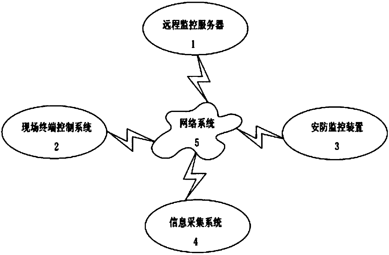
[0032] as attached Figure 1-7 As shown, the present invention is composed of a remote monitoring server 1, a field terminal control system 2, a security monitoring device 3, an information collection system 4 and a network system 5,

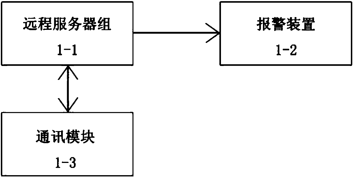
[0033] The remote monitoring server 1 includes a remote server group 1-1, an alarm device 1-2 and a communication module 1-3,

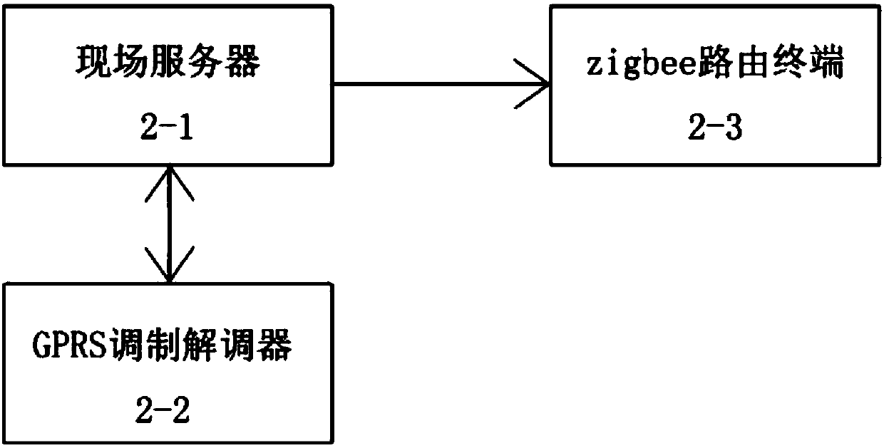
[0034] Described on-site terminal control system 2 is by on-site server 2-1, GPRS modem 2-2, zigbee routing terminal 2-3, and described on-site server 2-1 communicates with GPRS modem 2-2 and zigbee routing terminal 2-3 respectively through RS232 Interface connected;

[0035] The security monitoring device 3 includes a base plate 3-3 provided with a fixed slot 3-4, a pair of lead screws 3-6 parallel to both ends of the base plate 3-3, a vertical plate 3-13, a cover plate 3-1, Launcher 3-14, the lower end is provided with the first slide plate 3-7 of lead screw nut 3-6-1, the middle part is provided with the slide seat...


PUM


Abstract

The invention relates to a remote monitoring and control system for a security device, which is composed of a remote monitoring server, a site terminal control system, a security monitoring device, aninformation acquisition system and a network system, wherein the remote monitoring server includes a remote server group, an alarm device and a communication module; the site terminal control systemincludes a site server, a GPRS modem, and a zigbee routing terminal; and the site server is connected with the GPRS modem and the zigbee routing terminal through RS232 interfaces. The security monitoring system acquires needed information and then transmits the needed information to the site terminal control system for aggregation and transference through the network system and then the needed information is returned to the server for early warning and manual verification and at the same time, information sharing is carried out with a remote control end so that the needed information is timelyprocessed. The remote monitoring and control system for the security device is capable of networking flexibly and covering all areas reached by public networks.

Description

technical field [0001] The invention relates to a remote monitoring and control system for security equipment. Background technique [0002] In recent years, most parts of my country have suffered continuous heavy rainfall, and power facilities have suffered serious damage. Some are located in mountainous areas, and equipment such as small hydropower stations, 10kV distribution lines, and distribution transformers have been particularly damaged. The author now combines the self-rescue process of this flood to talk about the maintenance and precautions of the transformer grounding grid after the flood. The function of the transformer grounding grid (that is, the grounding device) is mainly to prevent personal electric shock, avoid equipment and line damage, prevent fire, prevent lightning strikes, prevent electrostatic damage, etc., and ensure the normal operation of the power system. The grounding down conductor of the lightning arrester, the metal shell of the distribution...

Claims


Application Information

Patent Timeline
IPC IPC(8): G05B19/048
Inventor 翟路海
Owner 西安玖诚玖谊实业有限公司
Why Eureka
Try Eureka