Supercharge Your Innovation With Domain-Expert AI Agents!

A bilateral flat permanent magnet linear motor

A permanent magnet linear motor, flat-plate technology, applied in electromechanical devices, electrical components, electric components, etc., can solve the problems of low thrust density and low acceleration, and achieve the effects of improving reliability, improving utilization, and easy fault-tolerant control.

Active Publication Date: 2020-09-01
HARBIN INST OF TECH
View PDF6 Cites 0 Cited by
  • Summary
  • Abstract
  • Description
  • Claims
  • Application Information

AI Technical Summary

Problems solved by technology

[0003] In order to solve the problems of low thrust density and low acceleration of existing permanent magnet synchronous linear motors, the present invention proposes a double-sided flat permanent magnet linear motor

Method used


Image

  • A bilateral flat permanent magnet linear motor
  • A bilateral flat permanent magnet linear motor
  • A bilateral flat permanent magnet linear motor

Examples


Embodiment approach 1

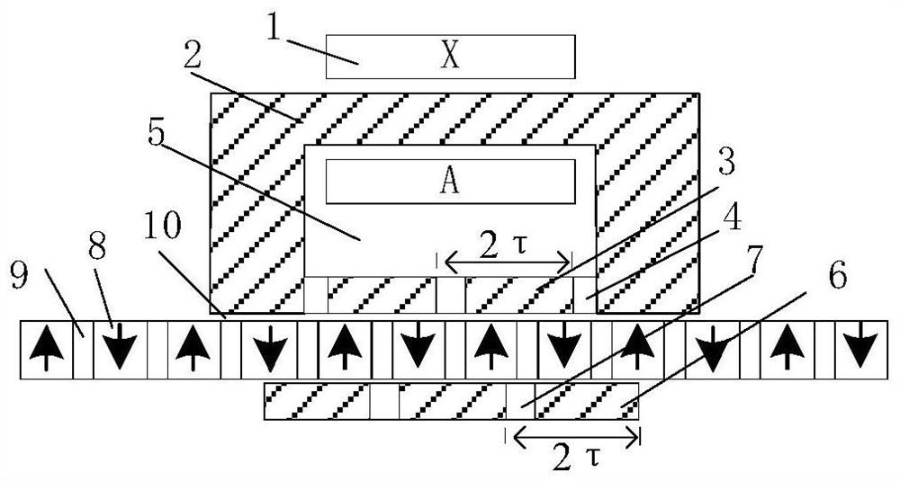
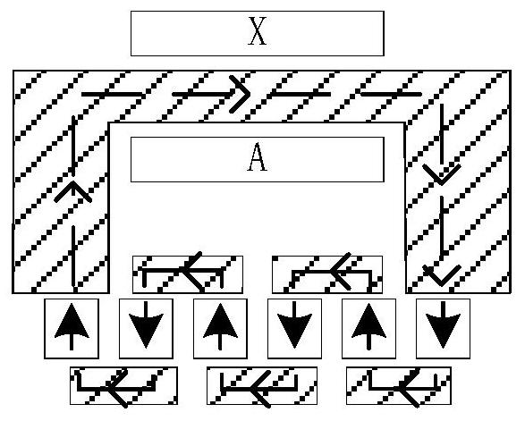
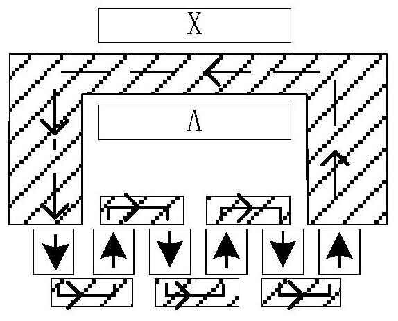
[0023] Such as figure 1 As shown, this embodiment is a single-phase motor, including primary, secondary and two air gaps. The upper primary is composed of an armature winding (1), a permeable core (2), an array of slotted permeable cores (3) and a gap (4) between the permeable cores. The permeable core (2) has an annular opening structure, and a large open slot (5) structure is formed inside, and the armature winding (1) is arranged in the slot, and is wound on the yoke of the permeable core (1). An array of permeable magnetic cores (3) is arranged in the notch along the horizontal direction. The distance between the magnetically permeable cores (3) in the array is 2τ, with a gap (4) in the middle. The lower primary is composed of permeable cores (6) with a salient pole structure and gaps (7), and the distance between adjacent permeable cores (6) is 2τ. The midpoint of the upper primary notch permeable core (3) corresponds to the midpoint of the lower primary gap (9). Cons...

Embodiment approach 2

[0028] Such as Figure 4 As shown, the difference between this embodiment and the first embodiment is that the first embodiment is a single-phase motor, and the third embodiment is a three-phase motor. This embodiment is a three-phase motor. The structures of the B-phase motor and the C-phase motor are exactly the same as that of the A-phase motor. It is (k±2 / 3)τ, K is a natural number. The winding adopts three-phase power supply, which can be sine wave or square wave power supply. The motor adopts a modular design, there is no electrical coupling between the phases, and the magnetic coupling is very small. When a winding failure of a certain phase does not affect other phases, it is easy to implement fault-tolerant control and is conducive to improving the reliability of the motor.


PUM


Abstract

The invention provides a bilateral flat plate type permanent magnet synchronous linear motor, belonging to the technical field of motors. The motor includes a primary component, a secondary componentand air gaps. The primary component includes an upper primary unit and a lower primary unit. The upper primary unit includes a plurality of large open-slot structures formed by magnetic conductive cores, and slots are provided with a discrete array of the magnetic conductive cores. The lower primary unit is formed by a magnetic conductive core with a salient pole structure and a gap, and the distance between two adjacent magnetic conductive cores is 2tau, which means that an array is formed according to the period of 2tau. A secondary unit is between the two primary units and is formed by a discrete permanent magnet array, and (2n+1) poles are arranged alternately according to N-S-N, and the pole distance is tau. Two air gaps are formed between the two primary units and the secondary unit.According to the motor, a three-layer design is adopted, the utilization rate of permanent magnets is which greatly improved, a large tooth space design is adopted, and the winding heat dissipation is facilitated and the design of a large electric load is adopted to further improve the thrust.

Description

technical field [0001] The invention belongs to the field of motors, and in particular relates to a double-sided flat permanent magnet linear motor. Background technique [0002] The direct transmission technology based on linear motors eliminates the need for intermediate complex transmission mechanisms. It has been applied in linear motion occasions such as machine tools and elevators, and its application fields are gradually expanding to various fields of production and life. However, unlike rotary motor systems, most direct-drive linear motor systems (except for high-speed and high-acceleration linear motors in electromagnetic ejection applications) cannot use high-speed designs to increase power density and reduce volume and mass. Therefore, it is necessary to reduce the volume of linear motors quality, we can only hope to increase the thrust density of the motor. Improving the thrust density of the motor can be considered from the aspects of increasing the electric lo...

Claims


Application Information

Patent Timeline
Patent Type & Authority Patents(China)
IPC IPC(8): H02K41/03
Inventor 谭强李立毅王明义黄旭珍
Owner HARBIN INST OF TECH
Features
  • R&D
  • Intellectual Property
  • Life Sciences
  • Materials
  • Tech Scout
  • Unparalleled Data Quality
  • Higher Quality Content
  • 60% Fewer Hallucinations
Learn More