A fully automatic assembly equipment for inductors

It is an assembly equipment and fully automatic technology, which is applied in mechanical equipment, metal processing equipment, and devices for coating liquid on the surface. It can solve problems such as condensation at the end of the core, easy overflow of glue, and impact on product quality. The effect of improving quality, reducing scrap rate and reducing production cost

Active Publication Date: 2020-05-26
利川市勤德电子科技有限公司
View PDF7 Cites 0 Cited by
  • Summary
  • Abstract
  • Description
  • Claims
  • Application Information

AI Technical Summary

Problems solved by technology

[0002] The so-called inductance coil is an electrical component often used in the circuit, which can provide appropriate inductance to the circuit. There are various methods for the inductance coil to control the provided inductance, and people have different requirements for the sealing, flame retardancy and safety of the inductance coil. It is getting higher and higher, and some existing inductance coils can no longer meet people's needs. With the development of science and technology, there are more and more inductance coils, and their functions are becoming more and more powerful.
[0003] In traditional work, it is usually manual to hold the inductance coil in one hand and the core in the other, and then bond them together. The inventor found that during the bonding molding process, the glue is easy to overflow and condense at the end of the core, affecting the product. quality problem

Method used


Image

  • A fully automatic assembly equipment for inductors
  • A fully automatic assembly equipment for inductors
  • A fully automatic assembly equipment for inductors

Examples


Embodiment 1

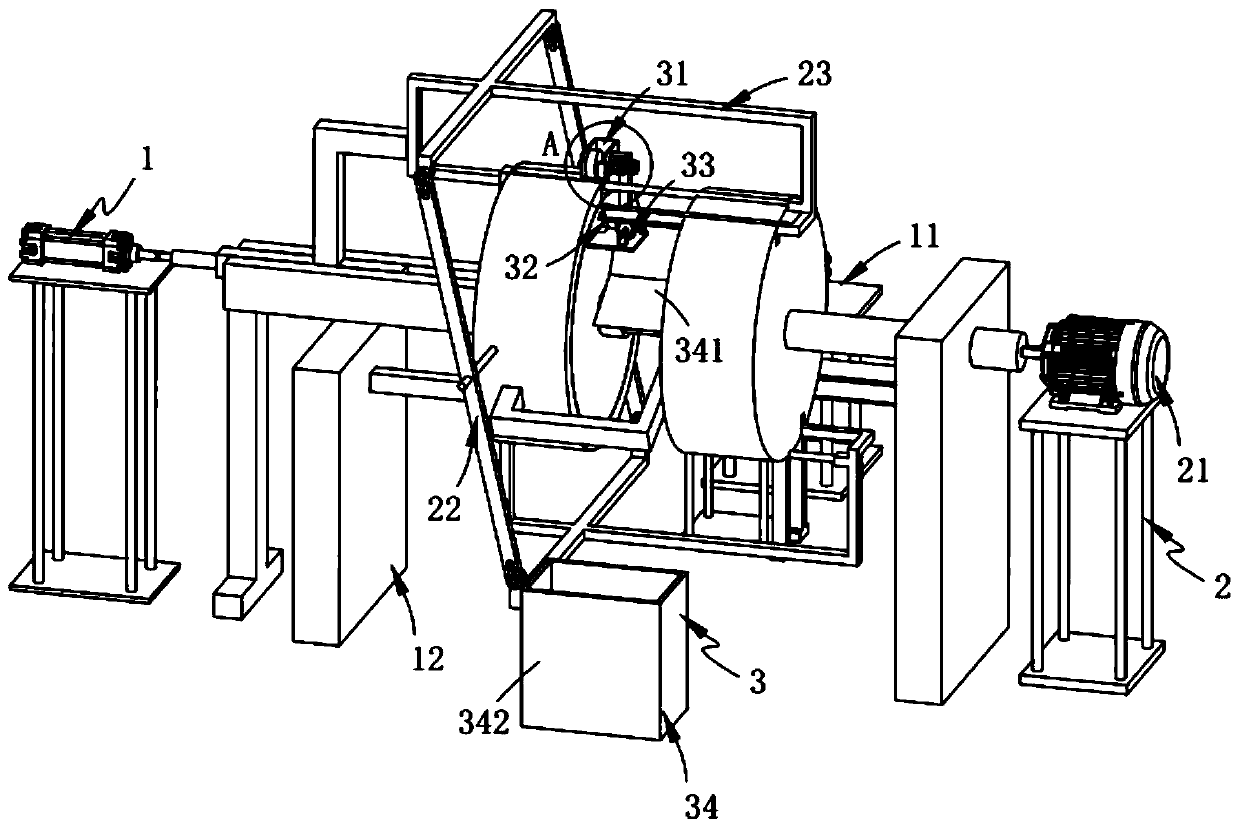
[0070] Such as figure 1 , Figure 11 with Figure 12 As shown, a fully automatic assembly equipment for inductors, including:

[0071] A feeding mechanism 1, the feeding mechanism 1 includes a coil upper assembly 11 and a magnetic core upper assembly 12 arranged perpendicularly to the coil upper assembly 11;

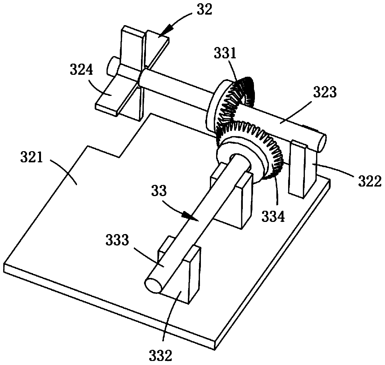
[0072] The station switching mechanism 2, the station switching mechanism 2 includes a rotating assembly 21 rotatably arranged on the magnetic core upper assembly 12, a transmission assembly 22 fixedly arranged on the rotating assembly 21 and symmetrically arranged, and the transmission assembly 22 connected with the transmission a reciprocating assembly 23 that is rotatably connected to the assembly 22 and slides horizontally along said rotating assembly 21; and

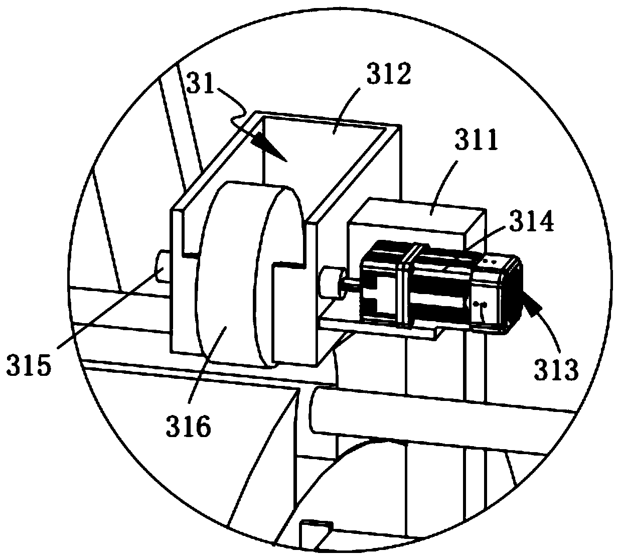
[0073] Forming and assembling mechanism 3, the forming and assembling mechanism 3 includes a gluing assembly 31 fixedly arranged on the magnetic core upper assembly 12 and located above the rotating assembl...

Embodiment 2

[0133] Such as figure 1 As shown, the parts that are the same as or corresponding to those in the first embodiment are marked with the corresponding reference numerals in the first embodiment. For the sake of simplicity, only the differences from the first embodiment are described below. The difference between this embodiment two and embodiment one is:

[0134] further, such as figure 1 As shown, the discharge plate 341 is arranged obliquely downward.

[0135] In this embodiment, by setting the output assembly 34, the fully assembled inductance coil is discharged to the material receiving bucket 342 in time along the inclined downwardly disposed discharge plate 341 for storage, and the whole device is continuous and complete.

[0136] work process:

[0137] First put the coils on the conveyor belt 1114 in turn, the coils are pushed onto the push plate 1123, start the cylinder a1121, and the coils are pushed to the front of the receiving shaft b2324; at this time, put the ma...


PUM


Abstract

The invention relates to fully automatic assembly equipment for an inductor. The fully automatic assembly equipment for the inductor comprises a loading mechanism, a station switching mechanism, and amolding assembly mechanism, wherein the loading mechanism comprises a shell upper loading assembly and a core upper loading assembly perpendicular to the shell upper loading assembly; the station switching mechanism comprises a rotating assembly arranged on the core upper loading assembly and rotationally arranged on the core upper loading assembly, a transmission assembly fixedly arranged on therotating assembly and symmetrically arranged and a reciprocating assembly rotationally connected with the transmission assembly and sliding horizontally along the rotating assembly; and the molding assembly mechanism comprises a gluing assembly, a glue scraping assembly fixedly arranged on the core upper loading assembly and located below the gluing assembly, a drive assembly connected with the reciprocating assembly and matching with the glue scraping assembly, and an output assembly fixedly connected with the gluing assembly and positioned below the glue scraping assembly; the fully automatic assembly equipment provided by the invention solves the technical problem that the glue overflows easily during the bonding forming process and condenses at the end of the core body, which affectsthe product quality.

Description

technical field [0001] The invention relates to the technical field of inductor coil materials, in particular to a fully automatic assembly device for inductors. Background technique [0002] The so-called inductance coil is an electrical component often used in the circuit, which can provide appropriate inductance to the circuit. There are various methods for the inductance coil to control the provided inductance, and people have different requirements for the airtightness, flame retardancy and safety of the inductance coil. The height is getting higher and higher, and some existing inductance coils can no longer meet people's needs. With the development of science and technology, there are more and more inductance coils, and their functions are becoming more and more powerful. [0003] In traditional work, it is usually manual to hold the inductance coil in one hand and the core in the other, and then bond them together. The inventor found that during the bonding molding p...

Claims


Application Information

Patent Timeline
Patent Type & Authority Patents(China)
IPC IPC(8): B23P19/04B05C1/02B05C11/02F16B11/00
Inventor 郑慧萌
Owner 利川市勤德电子科技有限公司
Why Eureka
Try Eureka