Paper pipe discharging device

A technology of unloading device and paper tube, which is applied in the direction of transportation and packaging, metal processing, conveyor objects, etc., can solve the problems of labor and low efficiency, and achieve the effect of high efficiency and simple structure

Inactive Publication Date: 2019-06-07
常州钟楼高新技术创业服务有限公司
View PDF0 Cites 3 Cited by
  • Summary
  • Abstract
  • Description
  • Claims
  • Application Information

AI Technical Summary

Problems solved by technology

[0003] The present invention improves the above-mentioned problems, that is, the technical problem to be solved by the present invention is that the existing paper tube unloading methods mostly use manual work, and the efficiency is low.

Method used


Image

  • Paper pipe discharging device
  • Paper pipe discharging device
  • Paper pipe discharging device

Examples


Embodiment Construction

[0011] The following will clearly and completely describe the technical solutions in the embodiments of the present invention with reference to the accompanying drawings in the embodiments of the present invention. Obviously, the described embodiments are only some, not all, embodiments of the present invention. Based on the embodiments of the present invention, all other embodiments obtained by persons of ordinary skill in the art without making creative efforts belong to the protection scope of the present invention.

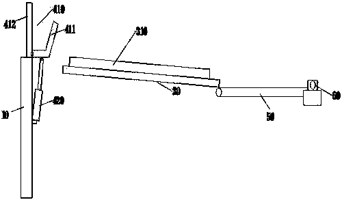
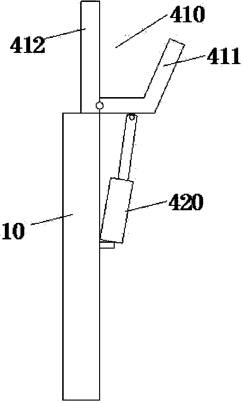
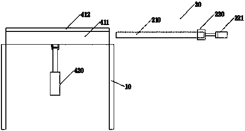
[0012] like Figure 1~4 As shown, a paper tube unloading device includes a frame 10 and a paper tube feeding device 20, and is arranged on an unloading platform 30 inclined at the front end of the paper tube feeding device 20. Above the unloading platform 30, a receiving The conveying device 20 pushes the feeding chute 410 of the paper tube. The feeding chute 410 includes a turn-shaped movable plate 411 and a vertically arranged fixed baffle 412. The rear end ...


PUM


Abstract

The invention discloses a paper pipe discharging device. The device comprises a rack, a paper pipe delivery device and a discharging platform which is obliquely arranged at the front end of the paperpipe delivery device, a delivery groove which is used for collecting paper tubes pushed by a transporting device is formed in the upper portion of the discharging platform, the delivery groove comprises a cornered moving plate and a vertically arranged fixing baffle, the rear side end of the moving plate is hinged to the fixing baffle, the lower end of the moving plate is provided with a driving air cylinder which is used for driving the moving plate to rotate around a hinge part, the driving air cylinder is fixed to the rack, and a telescopic rod of the driving air cylinder is hinged to the bottom of the moving plate. The device has the advantages that the structure is simple, the feeding of the paper tubes can be conveniently achieved to make subsequent hole punching of the paper tubes convenient, and the efficiency is high.

Description

technical field [0001] The invention relates to an unloading device, in particular to a paper tube unloading device. Background technique [0002] The paper tube described in the present invention is a central tubular structure used for winding films or cables. Its main material is recycled paper, etc. It is generally formed by multi-layer winding and bonding, so it needs to be dried after it is made. The traditional Paper tube forming is stacked by storage racks and then moved to other equipment for punching, which requires more manpower consumption and low efficiency. Contents of the invention [0003] The present invention improves the above-mentioned problems, that is, the technical problem to be solved by the present invention is that the existing paper tube unloading method mostly uses manual work, and the efficiency is low. [0004] The specific embodiment of the present invention is: a paper tube unloading device, including a frame and a paper tube feeding device,...

Claims


Application Information

Patent Timeline
IPC IPC(8): B26D7/06B65G47/06
Inventor 吴晗
Owner 常州钟楼高新技术创业服务有限公司
Why Eureka
Try Eureka