Cement blending device for hydraulic engineering construction

A water conservancy project and cement technology, which is applied in the field of cement blending devices for water conservancy project construction, can solve problems such as low mixing efficiency and inability to fully mix cement, and achieve the effects of improved processing effect, high promotion and practical value, and novel device structure

Inactive Publication Date: 2019-06-07
尹瑜
View PDF7 Cites 8 Cited by
  • Summary
  • Abstract
  • Description
  • Claims
  • Application Information

AI Technical Summary

Problems solved by technology

[0003] Water conservancy projects need to use a lot of cement in the construction process, manual mixing

Method used


Image

  • Cement blending device for hydraulic engineering construction
  • Cement blending device for hydraulic engineering construction
  • Cement blending device for hydraulic engineering construction

Examples


Example Embodiment

[0026] Example 1

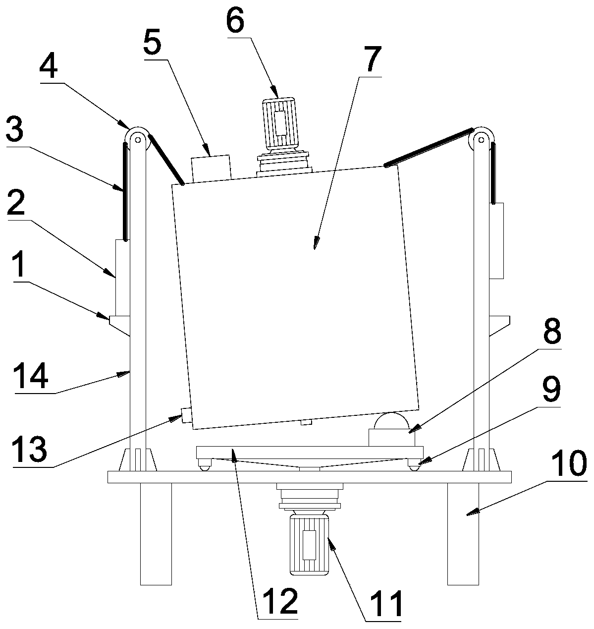
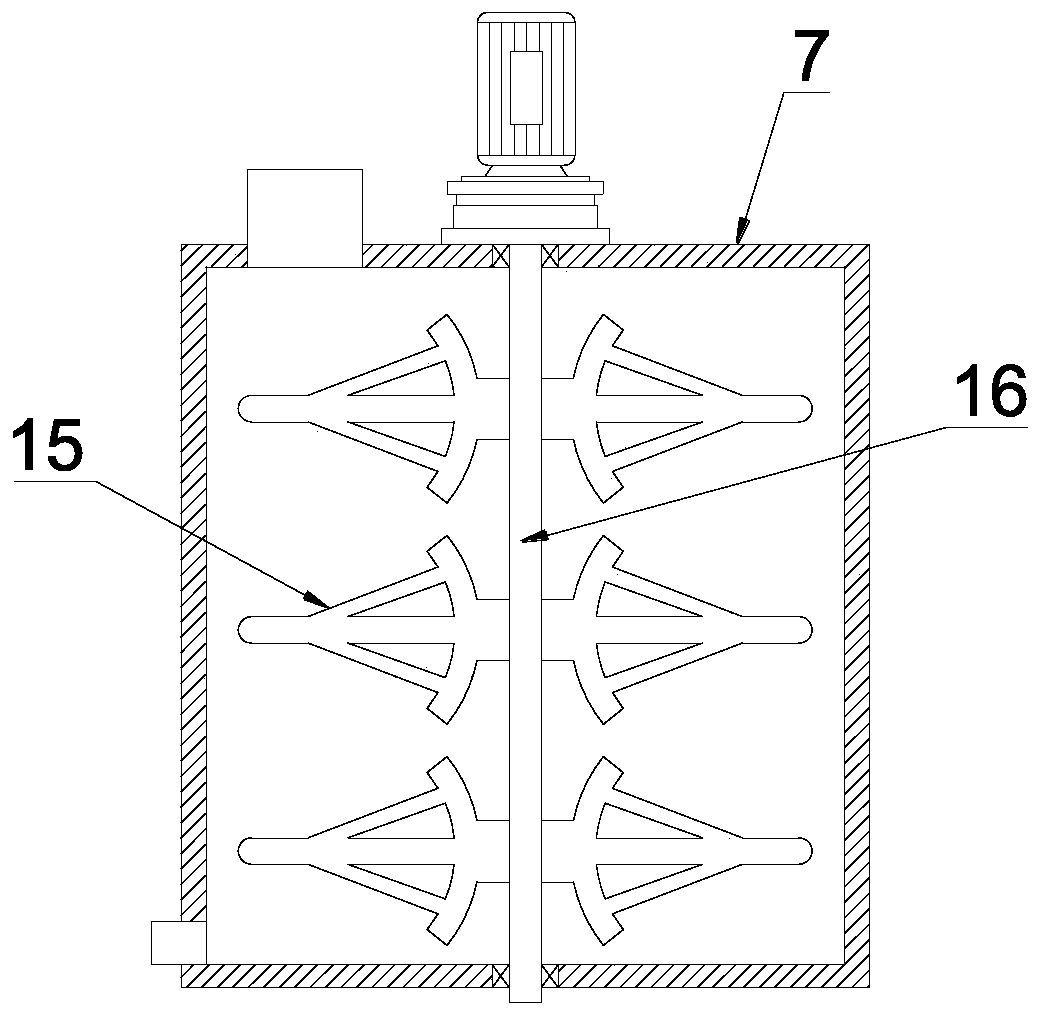
[0027] see Figure 1~3 , in an embodiment of the present invention, a cement blending device for water conservancy construction, comprising a blending box 7, a frame 10 and a column 14, the blending box 7 is a cylindrical cylinder structure with both ends sealed, and the top of the blending box 7 There is a material inlet 5, and the side bottom of the mixing box 7 is provided with a material outlet 13, the material inlet 5 and the material outlet 13 are respectively used for feeding and discharging, and the middle part of the mixing box 7 is provided with a stirring shaft 16 , the top and the bottom of the stirring shaft 16 and the mixing box 7 are sealed and rotated, and the top of the mixing box 7 is also provided with a first drive mechanism 6 for driving the stirring shaft 16 to rotate. A number of stirring assemblies 15 are installed on the shaft 16, and the first driving mechanism 6 can drive the stirring shaft 16 to rotate, and then drive the stirrin...

Example Embodiment

[0034] Example 2

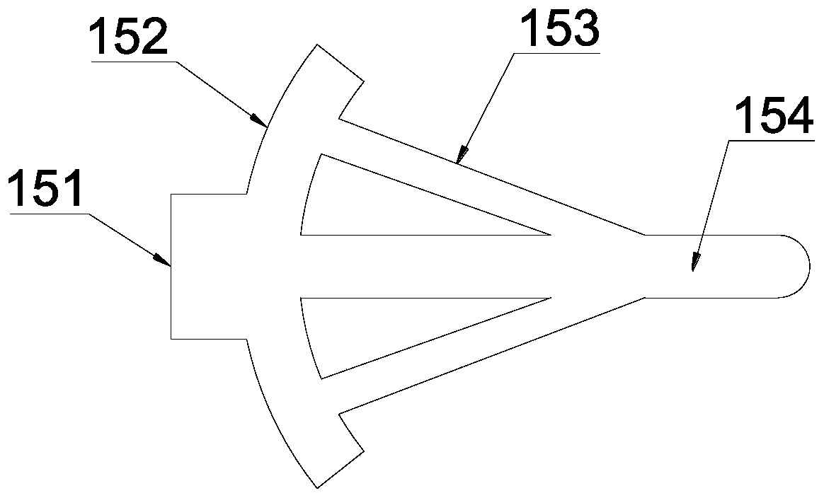
[0035] see figure 2 and 3 The difference between this embodiment and Embodiment 1 is that the stirring assembly 15 includes a fixing seat 151, an arc bar 152, a slanting bar 153 and a cross bar 154, and one side of the fixing seat 151 is fixed to the stirring shaft 16 On, the other side of fixed seat 151 is provided with arc-shaped bar 152, and arc-shaped bar 152 is the arc-shaped structure that both ends are away from stirring shaft 16, and the inner middle part of arc-shaped bar 152 is provided with cross bar 154, and the cross bar 154 The upper and lower sides are respectively provided with oblique rods 153, one end of the oblique rod 153 is fixed on the cross bar 154, the other end of the oblique rod 153 is fixed on the arc rod 152, and the distance between the oblique rod 153 and the cross rod 154 is 15-30 ° included angle, the fixed seat 151, the arc bar 152, the oblique bar 153 and the cross bar 154 are integrally processed and formed, and the stru...


PUM


Abstract

The invention discloses a cement blending device for hydraulic engineering construction. The device comprises a blending box, a rack and stand columns; a stirring shaft is arranged in the middle of the blending box, the top of the blending box is provided with a first driving mechanism used for driving the stirring shaft to rotate, multiple stirring assemblies are arranged at the position, on thestirring shaft, of the inner side of the blending box, the rack is arranged below the blending box, a rotating disc is arranged on the upper side of the rack, the rotating disc is driven by a second driving mechanism on the lower side of the rack to rotate, a first universal ball assembly used for enabling the blending box to incline is arranged on the outer ring of the upper side of the rotatingdisc, the stand columns are arranged on the outer ring of the top of the rack in the circumferential direction, guide wheels are arranged on the upper ends of the stand columns, a steel wire rope is wound on the guide wheels, one end of the steel wire rope is connected to the outer ring of the top of the blending box, and the other end of the steel wire rope is connected with the tops of weights on the outer sides of the stand columns. The cement stirring blending effect and efficiency can be improved, the device saves energy and is environmentally friendly, and the higher popularization and practicability value is achieved.

Description

technical field [0001] The invention relates to the field of hydraulic engineering construction equipment, in particular to a cement blending device for hydraulic engineering construction. Background technique [0002] Water conservancy projects are projects built to control and allocate natural surface water and groundwater to achieve the purpose of eliminating harm and rejuvenating profits, also known as water projects. Water is an indispensable precious resource for human production and life, but its natural state does not fully meet human needs. Only by building water conservancy projects can we control water flow, prevent floods, and regulate and distribute water to meet the needs of people's life and production for water resources. Water conservancy projects need to build different types of hydraulic structures such as dams, dikes, spillways, sluices, water inlets, channels, canals, rafts, and fishways to achieve their goals. [0003] Water conservancy projects need ...

Claims


Application Information

Patent Timeline
IPC IPC(8): B28C5/16B28C5/48
Inventor 尹瑜李清明钱晓梅李维陈健李建成王志苹孙艳孙晓波赵勇梁铎尹航尹玉荷
Owner 尹瑜
Why Eureka
Try Eureka