Drainage casing pipe capable of preventing odor and backflow

An anti-backflow and casing technology, which is applied in the direction of drainage structures, water supply devices, waterway systems, etc., can solve the problems of downward leakage, easy water accumulation, leakage, etc., to avoid water accumulation, prevent backflow, and prevent odor the emanating effect of

Pending Publication Date: 2019-06-07
成都煜明装饰工程有限公司
View PDF0 Cites 4 Cited by
  • Summary
  • Abstract
  • Description
  • Claims
  • Application Information

AI Technical Summary

Problems solved by technology

[0002] With the advancement of the policy of building industrialization, more and more construction projects adopt the same-layer drainage technology. It is the general trend to use the same-layer drainage technology for the floors. However, although the same-layer drainage solves the waterproof problem of the ground, it is often easy in the room. Water accumulation, long-term accumulation of water will seep downward along the ground finish layer to the structural slab surface, and eventually cause the structural layer to be in a water-logging environment for a long time, and there is a hidden danger of downward leakage
[0003] In the prior art, although the water stop sectio

Method used


Image

  • Drainage casing pipe capable of preventing odor and backflow
  • Drainage casing pipe capable of preventing odor and backflow
  • Drainage casing pipe capable of preventing odor and backflow

Examples


Embodiment 1

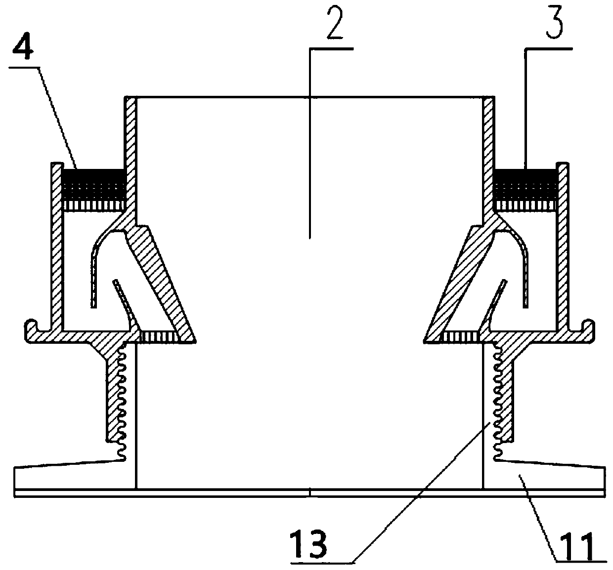
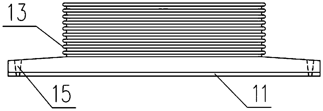
[0036] Such as figure 1 , image 3 and Figure 4 As shown, a drainage casing capable of deodorizing and preventing backflow includes a horizontally arranged chassis 11 and a vertically arranged casing 13, the chassis 11 is provided with a through hole, and the bottom end of the casing 13 is connected to the bottom of the casing 13. The top surface of the chassis 11 is fixedly connected, and the through hole communicates with the inner cavity of the sleeve 13, and the top of the sleeve 13 is provided with a drainage and water-stop joint device 2 capable of deodorizing and preventing backflow. The water section device 2 is sheathed with an annular drainage screen device 3 capable of filtering impurities.

[0037] Specifically, the diameter of the sleeve 13 is smaller than the diameter of the chassis 11 , and the chassis 11 is provided with a mounting hole 15 , and the mounting hole 15 is provided with a screw for fixing the chassis 11 .

[0038] Specifically, the drainage wat...

Embodiment 2

[0044] Such as Figure 5 and Figure 6 As shown, the difference from Embodiment 1 is that the annular drainage screen device 3 includes an outer ring 31, an inner ring 32 and eight third connecting posts 33, and the diameter of the inner ring 32 is smaller than that of the outer ring 31. diameter, the inner side of the inner ring 32 abuts against the outer side of the top collar 21, the outer side of the inner ring 32 is connected to the inner side of the outer ring 31 through eight third connecting posts 33, and the outer ring 31 abuts against the inner side of the outer wall sleeve 24 , and the gap formed by the inner ring 32 , outer ring 31 and eight third connecting columns 33 is filled with a filter screen 34 . The eight third connecting columns 33 are arranged at equal intervals.

[0045] Specifically, a sponge pad 4 is provided on the bottom surface of the filter screen 34 , and the sponge pad 4 is fixedly connected with the top sleeve 21 and the outer wall sleeve 24 ...

Embodiment 3

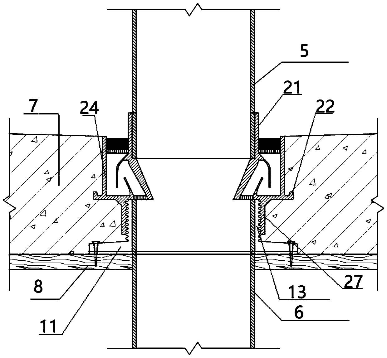
[0048] Such as figure 2 As shown, the difference from Example 1 is that the present invention is generally pre-embedded in the structural slab 7 during the structural construction process. When in use, the screws pass through the mounting holes 15 to fix the chassis 11 on the formwork 8, and after being fixed in place, the Brush the pipe special glue on the casing 13 on the chassis 11, screw the bottom casing 27 with the casing 13 and screw it into the casing 13, adjust the height of the outer wall casing 24 according to the thickness of the structural layer 7 during the screwing process It is the same height as the top surface of the structure layer 7 and the mechanism layer 7. Then, before concrete pouring, protective measures can be taken for the present invention. The protective measures refer to a preventive measure taken during the concrete pouring process to prevent slurry or aggregate from flowing into the present invention. Further protective measures can be adopted ...


PUM


Abstract

The invention relates to a connecting part capable of enabling an upper pre-connection pipeline and a lower connection pipeline to communicate in a same layer drainage process, in particular to a drainage casing pipe capable of preventing odor and backflow. The drainage casing pipe capable of preventing odor and backflow comprises a horizontally arranged chassis and a vertically arranged casing pipe, wherein a through hole is formed in the chassis; the bottom end of the casing pipe is fixedly connected with the top surface of the chassis, and the through hole communicates with an inner cavityof the casing pipe; a drainage water stop joint device capable of deodorizing and preventing backflow is arranged on the top end of the casing pipe in a sleeving mode; and an annular drainage filter screen device capable of filtering impurities is arranged on the drainage water stop joint device in a sleeving mode. The drainage water stop joint device removes accumulated water of a floor through agap formed between an inner wall casing pipe and an outer wall casing pipe, liquid sealing is realized through a water stop ring part and a water proof ring part, and meanwhile, backflow caused by different air pressures is prevented. The drainage casing pipe capable of preventing odor and backflow has rich functions, the structure is simple, the installation is convenient, construction steps andmaterials are saved, and the functions of deodorization and backflow prevention while drainage can be realized.

Description

technical field [0001] The invention relates to a connecting part capable of connecting an upper pre-connected pipe and a lower connected pipe in the drainage process of the same floor, in particular to a drainage casing capable of deodorizing and preventing backflow. Background technique [0002] With the advancement of the policy of building industrialization, more and more construction projects adopt the same-layer drainage technology. It is the general trend to use the same-layer drainage technology for the floors. However, although the same-layer drainage solves the waterproof problem of the ground, it is often easy in the room. Water accumulation, long-term accumulation of water will seep downward along the ground finish layer to the structural slab surface, and eventually the structural layer will be in a water-logging environment for a long time, and there is a hidden danger of downward leakage. [0003] In the prior art, although the water stop section is used to op...

Claims


Application Information

Patent Timeline
IPC IPC(8): E03F5/04E03F5/042E03F5/14
Inventor 姚洪玉罗成张勇李福川
Owner 成都煜明装饰工程有限公司
Why Eureka
Try Eureka