Supercharge Your Innovation With Domain-Expert AI Agents!

Novel hollow grouting anchor cable and manufacturing method thereof

A grouting anchor cable and hollow technology, which is used in earth-moving drilling, installation of anchor rods, mining equipment, etc. The effect of uneven force, advanced production technology and simple production technology

Inactive Publication Date: 2019-06-07
山东焱鑫矿用材料加工有限公司
View PDF3 Cites 3 Cited by
  • Summary
  • Abstract
  • Description
  • Claims
  • Application Information

AI Technical Summary

Problems solved by technology

[0005] 1. It is used to prevent the strands from being broken. After twisting, the two ends of the strands need to be welded by a welding machine. The welding will lead to cumbersome production processes, and often the quality of the welding is different due to the quality of the process, resulting in the installation and stirring. Welding, resulting in failure of the anchor cable;
[0006] 2. The special mixing head for the car is generally hexagonal, with a hole in the middle and a hole of unequal diameter. Both diameters need to be threaded. One is to connect with the grouting pipe, and the other is to connect with the grouting equipment and plugging wire. connection, making the manufacturing process more cumbersome and increasing the cost;
[0007] 3. During twisting, each steel wire is likely to cause serious concentricity deviation, which eventually leads to uneven stress on each steel wire of the steel strand, which causes a single steel wire to be broken when it is stressed, so that the maximum performance of the anchor cable cannot be exerted. Less than the purpose of high-strength support;
[0008] 4. The performance of the anchor cable is poor. Taking the most commonly used SKZ22-1 / 1860 as an example, the maximum force of the steel strand is only about 420kN, so the design bearing capacity of the anchor cable is only 252kN, the strength of the anchor cable is low, and the steel strand is the largest The elongation rate is only 3.5%, and the elongation rate is reduced, which is not suitable for the support requirements of coal mine roadway

Method used


Image

  • Novel hollow grouting anchor cable and manufacturing method thereof
  • Novel hollow grouting anchor cable and manufacturing method thereof
  • Novel hollow grouting anchor cable and manufacturing method thereof

Examples


Embodiment Construction

[0030] In order to make the purpose, technical solutions and advantages of the embodiments of the present invention clearer, the technical solutions in the embodiments of the present invention will be clearly and completely described below in conjunction with the drawings in the embodiments of the present invention. Obviously, the described embodiments It is a part of embodiments of the present invention, but not all embodiments. The components of the embodiments of the invention generally described and illustrated in the figures herein may be arranged and designed in a variety of different configurations. Accordingly, the following detailed description of the embodiments of the invention provided in the accompanying drawings is not intended to limit the scope of the claimed invention, but merely represents selected embodiments of the invention. Based on the embodiments of the present invention, all other embodiments obtained by persons of ordinary skill in the art without cre...


PUM


Abstract

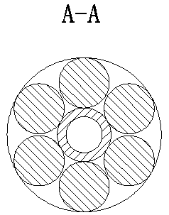
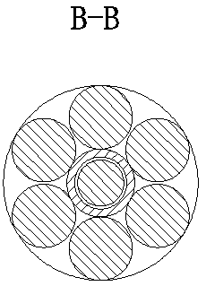
The invention discloses a novel hollow grouting anchor cable and a manufacturing method thereof. The novel hollow grouting anchor cable comprises a grouting section and an anchoring section, wherein that grouting section comprises a metal grouting pipe, a nonmetallic grouting pipe and a hollow steel strand; a cap nut is connected to one end of the metal grouting pipe through threads; the groutingsection further comprises a mine anchor cable anchorage device and an anchor cable tray which are arranged on the hollow steel strand; a grouting-stop plug and a grouting-stop plug push pipe are further arranged on the outer side of the hollow steel strand; and the metal grouting pipe is connected with the nonmetallic grouting pipe; and a supporting sleeve is arranged at one end of the nonmetallicgrouting pipe, the supporting sleeve is arranged at the middle position of the hollow steel strand, a slurry outlet is formed between the grouting section and the anchoring section, the anchoring section comprises an outer layer steel strand and a core steel wire, and the core steel strand is further provided with a supporting sleeve, so that welding fixation is not required, the stress is uniform, the stability is good, and the performance is high.

Description

technical field [0001] The invention relates to the technical field of roadway anchor cable support, in particular to a novel hollow grouting anchor cable and a manufacturing method thereof. Background technique [0002] Anchor cable support has the characteristics of large anchoring radius, strong anchoring force, and wide reinforcement range. plays an important role in. [0003] Anchor cable support is to install anchor cables in the surrounding rock to form an anchor body to strengthen the surrounding rock and improve the bearing capacity of the surrounding rock. [0004] The current hollow grouting anchor cables are prone to the following disadvantages due to the deficiencies in production equipment and technology: [0005] 1. It is used to prevent the strands from being broken. After twisting, the two ends of the strands need to be welded by a welding machine. The welding will lead to cumbersome production processes, and often the quality of the welding is different d...

Claims


Application Information

Patent Timeline
IPC IPC(8): E21D21/00E21D20/02
Inventor 巩春海朱涛刘胜虎张德稳李晨尹义军林学贞吴秀亮
Owner 山东焱鑫矿用材料加工有限公司
Features
  • R&D
  • Intellectual Property
  • Life Sciences
  • Materials
  • Tech Scout
  • Unparalleled Data Quality
  • Higher Quality Content
  • 60% Fewer Hallucinations
Learn More