
Air inlet device and smokeless cooking system

A technology of air intake device and flue gas, which is applied in wind power generation, oil fume removal, wind power engine, etc. It can solve the problems of high flue gas reuse rate and single function of air intake device, and achieve high energy reuse rate and smoking effect Good, improve the effect of user experience

Pending Publication Date: 2019-06-07
CHONGQING XUNNENG ENERGY SAVING GAS EQUIP
View PDF0 Cites 0 Cited by
  • Summary
  • Abstract
  • Description
  • Claims
  • Application Information

AI Technical Summary

Problems solved by technology

[0003] The object of the present invention is to aim at the existing technical status, to provide a kind of air inlet device, its oil absorption effect is good, the reutilization rate of flue gas is high, and the flue gas can be reused for rotation and further used for power generation and light emission, etc. It is conducive to all-round personalized display of products, and effectively solves the problem of single function of the air intake device of the smokeless cooking system

Method used


Image

  • Air inlet device and smokeless cooking system
  • Air inlet device and smokeless cooking system
  • Air inlet device and smokeless cooking system

Examples


Embodiment 1

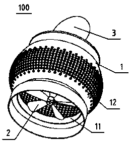
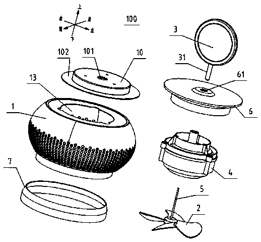
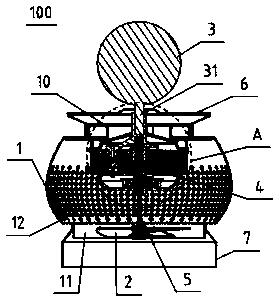
[0026] Such as figure 1 As shown, an air inlet device 100 of this embodiment includes a casing 1 , an impeller 2 and a display stand 3 . The casing 1 is provided with an air outlet 11 for exhausting the smoke, and its peripheral wall is provided with an air inlet 12 for passing the smoke. The impeller 2 is rotatably arranged in the casing 1 . The display stand 3 is rotatably connected to the top of the housing 1, and is used to provide a unique brand and corporate image display stand. The impeller 2 rotates under the action of wind energy generated by the flue gas flow, and then can drive the display stand 3 to rotate. Preferably, the impeller 2 is coaxial and arranged close to the air outlet 11, so that when the smoke is sucked into the casing 1 and flows out of the air outlet 11, the impeller 2 can be rotated under the action of the smoke flow and can drive the display Table 3 rotates. Thus, the air intake device 100 not only has a smoking function, but also makes full u...

Embodiment 2

[0038] like Figure 6 As shown, a smokeless cooking system of this embodiment includes a cooking system body 200 and a suction purification device (not shown in the figure) arranged in the cooking system body 200, which also includes the advanced The wind device 100 is provided with an air inlet end 201 and a smoke outlet 202 on the cooking system body 200 , the air inlet device 100 is connected to the top of the cooking system body 200 , and the air guide ring 7 communicates with the air inlet end 201 . Specifically, the air inlet end 201 is arranged at the top center of the cooking system body 200, and it communicates with the air suction and purification equipment.

[0039] Thus, under the action of the air suction and purification equipment, the smoke generated by cooking is sucked into the casing 1 in all directions at 360 degrees, flows through the impeller 2, flows out from the air outlet 11, and enters through the air guide ring 7 and the air inlet end 201. The inside...


PUM


Abstract

The invention discloses an air inlet device. The air inlet device comprises a shell, an impeller and a display stand, wherein the shell is provided with an air outlet and an air inlet; the impeller isrotatably arranged in the shell; the display stand is rotatably connected to the top of the shell; and the impeller rotates under the action of wind energy generated by flue gas flow and can drive the display stand to rotate. The invention further discloses a smokeless cooking system with the air inlet device applied. The air inlet device has the following advantages that 1, the smoke is reused for rotation, and further used for generating power and light and the like, so that the air inlet device has an advertisement display function to facilitate comprehensive and individualized display ofbrand and enterprise image of products, and the purposes of energy conservation and emission reduction are achieved; and 2, the smokeless cooking system has the advantages of good smoke extraction effect, high energy recycling rate, individualized brands and image display positions and the like, provides personalized selections for customers, and is beneficial to improving user experience.

Description

technical field [0001] The invention relates to the technical field of smokeless cooking systems, in particular to an air intake device and a smokeless cooking system using flue gas to generate electricity. Background technique [0002] During the frying, frying, deep-frying and roasting of food, a lot of oil fume will be produced. In order to improve the cooking environment and protect human health, range hoods are often used to purify the oil fume. The air intake device of the existing range hood is usually an oil screen assembly, but the function of this type of range hood is relatively single, which is not conducive to the personalized display of the brand and the promotion of the corporate image. Moreover, the oily fume generated during the cooking process is sucked into the hood and directly discharged outside after purification, which has no effect and is extremely unfavorable for energy saving and emission reduction. Contents of the invention [0003] The object o...

Claims


Application Information

Patent Timeline
Patent Type & Authority Applications(China)
IPC IPC(8): F24C15/20F03D9/20
CPCY02E10/72
Inventor 贾明清
Owner CHONGQING XUNNENG ENERGY SAVING GAS EQUIP
Learn More