Anti-rotation device, motion table system and photolithography equipment

An anti-rotation and workpiece table technology, applied in the field of photolithography, can solve the problems of cable pipeline hazards, workpiece table cannot be moved, workpiece table loses positioning ability, etc., and achieve the effect of avoiding resistance

Active Publication Date: 2021-06-04
SHANGHAI MICRO ELECTRONICS EQUIP (GRP) CO LTD
View PDF4 Cites 0 Cited by
  • Summary
  • Abstract
  • Description
  • Claims
  • Application Information

AI Technical Summary

Problems solved by technology

[0004] Among them, the polarization direction of the stator magnet and the magnetic pole direction generated by the coil of the workpiece table must maintain a certain spatial relationship, otherwise the workpiece table will lose its positioning ability
Based on this spatial relationship, if the workpiece table rotates 45° in the event of software failure or program error, collision, power loss, etc., and the direction of the magnetic field generated by the coil is parallel to the direction of the magnetic field of the magnet in the moving platform, the workpiece table will not be able to movement, and at the same time, this large rotation can cause damage to the cable ducts connected to the workpiece table

Method used


Image

  • Anti-rotation device, motion table system and photolithography equipment
  • Anti-rotation device, motion table system and photolithography equipment

Examples


Embodiment Construction

[0055]The following will clearly and completely describe the technical solutions in the embodiments of the present invention with reference to the accompanying drawings in the embodiments of the present invention. Obviously, the described embodiments are only some, not all, embodiments of the present invention. Based on the embodiments of the present invention, all other embodiments obtained by persons of ordinary skill in the art without making creative efforts belong to the protection scope of the present invention.

[0056] The technical solution of the present invention will be described in detail below with specific embodiments. The following specific embodiments may be combined with each other, and the same or similar concepts or processes may not be repeated in some embodiments.

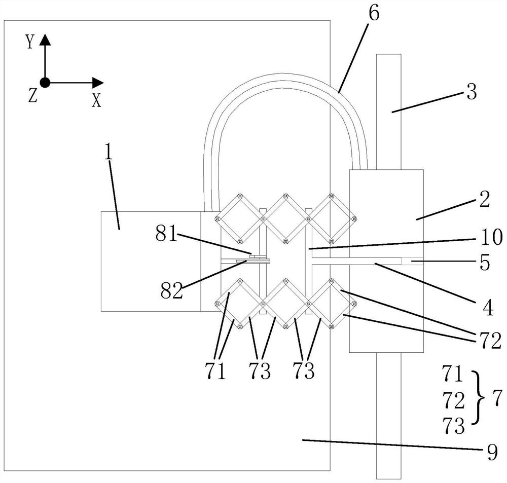
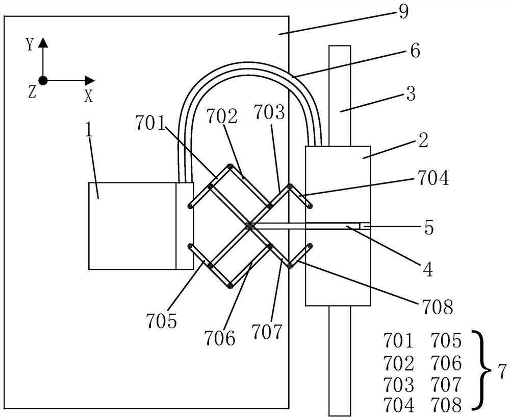
[0057] figure 1 It is a structural representation of a motion platform system of the present invention Figure 1 ; figure 2 It is a structural representation of a motion platform system of...


PUM


Abstract

The present invention provides an anti-rotation device, a motion table system and a lithography equipment. The anti-rotation device is connected between the workpiece table and the cable table, and is used to limit the workpiece table relative to the cable table around the plane where the vertical workpiece table is located. When the axis of the shaft rotates at an unexpected angle, the anti-rotation device includes a cross telescopic link assembly, and the two ends of the cross telescopic link assembly are respectively connected to the workpiece table and the cable table in rotation; when the workpiece table moves along the first direction, the cross telescopic linkage The rod assembly can be compressed or extended in the same direction, and the connection position of the cross telescopic link assembly, the workpiece table and the cable table remains unchanged in the second direction, and the first direction is the shortest connection direction between the workpiece table and the cable table , the second direction is perpendicular to the first direction in the same plane. When the cross-telescopic connecting rod assembly of the present invention is stretched, its connection position with the workpiece table and the cable table remains unchanged, so as to avoid resistance to the movement of the motion table due to the movement of the connection point along the non-telescopic direction.

Description

technical field [0001] The invention relates to the field of lithography, in particular to an anti-rotation device, a moving table system and lithography equipment. Background technique [0002] In semiconductor lithography equipment, precision workpiece stage motion systems such as silicon wafer stage and mask stage are extremely important key components. [0003] In the existing related technology, a planar magnetic levitation motor can be used to realize a long-stroke coarse movement precision workpiece table motion system, wherein the precision workpiece table motion system includes a motion platform (a stator formed by a plurality of magnets arranged in a certain way) and Consists of a workpiece table containing conductive coils. [0004] Among them, the polarization direction of the stator magnet and the magnetic pole direction generated by the coil of the workpiece table need to maintain a certain spatial relationship, otherwise the workpiece table will lose its posi...

Claims


Application Information

Patent Timeline
Patent Type & Authority Patents(China)
IPC IPC(8): G03F7/20
Inventor 赵灿武
Owner SHANGHAI MICRO ELECTRONICS EQUIP (GRP) CO LTD
Why Eureka
Try Eureka