Intelligent control network system, cloud platform and intelligent gateway device

A technology of intelligent control and intelligent gateway, applied in transmission systems, electrical components, data exchange through path configuration, etc., can solve the problem that lamps cannot be added to the network, and achieve the effect of saving debugging costs

Active Publication Date: 2019-06-07
SHANGHAI YAMING LIGHTING +1
10 Cites 2 Cited by

AI-Extracted Technical Summary

Problems solved by technology

[0010] Problem 1 (Cross-site network access): New lamps at site A are automatically added to the gateway network at site B during the network establishment phase. The resulting problem is that some lamps at site A must pass through the gateway at site B to be controlled. It is not allowed in the application, because the gateway at site A controls the lamps at site A, and the gateway at site B controls the lamps at site B, which is the basic lighting application requirement
[0011] Problem 2 (network stealing lights): At the beginning, the lamps and lanterns of site A work normally in the gateway network of site A, but then in the initial installation stage of the control system of si...

Method used

Can be connected by the dual-mode communication mode of PLC and micropower wireless between described intelligent gateway equipment 104 and each intelligent terminal 103, the mode of dual-mode fusion can improve reliability; Optionally, each described intelligent control The personal ar...

Abstract

The invention discloses an intelligent control network system, a cloud and an intelligent gateway device. Each intelligent gateway device is arranged to allow the intelligent terminal to access the network in a network access time window which is not overlapped with other adjacent or nearby intelligent gateway devices. each intelligent control personal area network is established under the condition that each intelligent terminal in the field to which the intelligent gateway device only allows the intelligent terminal to access the network is powered on and can access the network; Namely, theproblem of cross-site network access is solved through the power-on sequence of the intelligent terminal accessed to each domain network and the automatic network access strategy of the network accesstime window; In addition, network lamp stealing can be avoided in the mode that the network identifiers of the domain networks are endowed to the intelligent terminals of the domain networks and cannot enter other domain networks, the two-dimensional code process of setting a white list and pasting an MAC address in the prior art is not needed, high efficiency and simplicity are achieved, and thedebugging cost is saved.

Application Domain

Technology Topic

Image

  • Intelligent control network system, cloud platform and intelligent gateway device
  • Intelligent control network system, cloud platform and intelligent gateway device
  • Intelligent control network system, cloud platform and intelligent gateway device

Examples

  • Experimental program(1)

Example Embodiment

[0037] The following describes the implementation of the present application through specific specific examples, and those skilled in the art can easily understand other advantages and effects of the present application from the content disclosed in this specification. This application can also be implemented or applied through other different specific embodiments, and various details in this specification can also be modified or changed based on different viewpoints and applications without departing from the spirit of the application. It should be noted that the embodiments in this application and the features in the embodiments can be combined with each other if there is no conflict.
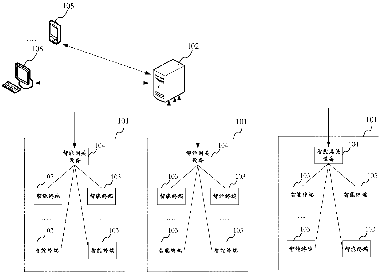
[0038] In the intelligent control network system, each domain network needs to consider how to distinguish the correct access of the intelligent terminal belonging to each domain network when constructing the network, so as to solve the problem of "cross-site access to the network". Whether the smart terminal connected to the network belongs to the network, so as to solve the problem of "network stealing lights".
[0039] Such as figure 1 As shown, the structure diagram of the intelligent control network system in the embodiment of the present application is shown.
[0040] The intelligent control network system includes multiple intelligent control personal area networks 101 and a cloud intelligent management and control platform 102.
[0041] In this embodiment, each intelligent control personal area network 101 is distributed in different sites. Specifically, the intelligent control network system can be applied to an indoor environment, such as an office building, a shopping mall, a school, etc., and each site can be a neighboring area in the same indoor environment, such as different areas on the first floor (such as office areas). , Business districts or teaching districts, etc.), or different layers; each of the intelligent control personal area networks 101 is distributed in these adjacent areas one by one.
[0042] In this embodiment, each of the intelligent control personal area networks 101 includes: a plurality of intelligent terminals 103 arranged in the corresponding site, and an intelligent gateway device 104 communicatively connected with each intelligent terminal 103. Wherein, the smart terminal 103 may be a smart lamp or a control panel, etc. The smart lamp includes one or more forms of a bulb lamp, a pendant lamp, a spot lamp, a flat lamp, and a light strip.
[0043] The smart gateway device 104 and each smart terminal 103 can be connected by PLC and micro-power wireless dual-mode communication. The dual-mode integration can improve reliability; optionally, each of the smart control personal area networks 101 may also include a control panel installed in the field, which can also be connected to each smart terminal 103 through a dual-mode communication method of PLC and micro-power wireless for users to adjust the lighting of each smart terminal 103 on site.
[0044] In this embodiment, the cloud intelligent management and control platform 102 and each smart gateway device 104 are connected through a TCP/IP network, which may be a wired network connection, a wireless network connection, or a combination of wired and wireless networks.
[0045] Wherein, the cloud intelligent management and control platform 102 is connected to each intelligent gateway device 104 to collect information of the intelligent terminal 103 in each intelligent control personal area network 101, and is also used to issue instructions to each intelligent control personal area network 101 for management and control. Each smart terminal 103.
[0046] Optionally, the smart control personal area network 101 can be accessed by a user's smart device 105, and the smart device 105 is a device with processing and communication capabilities, such as smart phones, tablet computers, desktop computers, notebook computers, VR /AR helmets or glasses, vehicle terminals or other equipment, not listed here; users connect to the Internet through the Internet (such as TCP/IP wired or wireless network, such as WiFi, 2G/3G/4G/5G mobile communication network, etc.) The cloud intelligent management and control platform 102 can issue instructions so as to control each of the intelligent terminals 103 through the cloud intelligent management and control platform 102.
[0047] In the above embodiments, the so-called intelligence refers to the information processing and communication capabilities integrated in the device. Electronic devices can be integrated in the cloud intelligent management and control platform 102, the intelligent gateway device 104, the intelligent terminal 103, and the intelligent device 105 to realize "intelligence".
[0048] Such as figure 2 As shown, a schematic structural diagram of the electronic device 200 in the embodiment is shown.
[0049] The electronic device 200 includes: a transceiver 201, a memory 202, and a processor 203.
[0050] The transceiver 201 is used to communicate with the outside;
[0051] The memory 202 is used to store a computer program; the processor 203 is coupled to the transceiver 201 and the memory 202 and is used to run the computer program to implement required functions.
[0052] In an embodiment, the transceiver 201 may include an interface, such as a serial port (such as RS485, RS232, etc.), a network port (RJ45), and any one or more wired interfaces of a USB interface, and may also include, for example, WiFi, NB -IOT, LoRA, Bluetooth or 2G/3G/4G/5G mobile communication circuit, etc.
[0053] The memory 202 may include a random access memory (Random Access Memory, RAM for short), and may also include a non-volatile memory (non-volatile memory), such as ROM, or disk memory.
[0054] The processor 203 may include a central processing unit (Central Processing Unit, CPU), a network processor (Network Processor, NP), etc.; it may also be a digital signal processor (Digital Signal Processing, DSP), an application specific integrated circuit (Application Specific Integrated Circuit, ASIC for short), Field-Programmable GateArray (FPGA for short) or other programmable logic devices, discrete gates or transistor logic devices, discrete hardware components.
[0055] Such as image 3 As shown, a schematic diagram of the process of establishing each domain network in the embodiment of the present application is shown. The process of this embodiment can be applied to, for example figure 1 The establishment of each intelligent control personal area network in the shown intelligent control network system can be referred to as "automatic network access strategy of power-on sequence and network access window control".
[0056] The process specifically includes:
[0057] Step S301: During network construction, the cloud intelligent management and control platform issues instructions to an intelligent gateway device to set information about a time window for network access;
[0058] Step S302: The smart gateway device allows the smart terminal to access the network within the network access time window.
[0059] In an embodiment, the smart gateway device may continuously send a network access request within the network access time window to obtain a response from the smart terminal.
[0060] Step S303: The user powers on the smart terminal to be networked on site.
[0061] In one embodiment, for the construction of adjacent lighting sites in the same building, electrical installers first uniformly complete the installation of the smart control system on all sites and the simple power-on switch test in each site to confirm whether the lamps are Damaged and whether the electrical wiring is correct (Note: Every lighting site generally has a conventional electrical switch or power distribution control switch.) Step S304: The powered-on smart terminal is connected to the smart gateway device and connected to the network.
[0062] At this point, the establishment of an intelligent control personal area network can be completed.
[0063] It is understandable that the cloud intelligent management and control platform can issue non-overlapping network access time windows to each smart gateway device, and cooperate with each smart gateway device to start networking before the corresponding smart gateway device is to be networked. The terminal is powered on, so that each intelligent control personal area network can be networked in chronological order, without the problem of "cross-site access".
[0064] In order to solve the problem of "light stealing from the network", in the development of the application layer protocol of the intelligent control network system, a "network identifier (PanID)" can be defined and used to identify the intelligent terminal in the personal area network formed by the intelligent gateway device ( For example, for the status of smart lamps and lanterns and/or control panels, each personal area network can be assigned a unique network identifier for the cloud intelligent management and control platform.
[0065] For example, at the lighting project site, a new smart terminal that has not successfully connected to the network has its internal embedded firmware (firmware) that saves the factory initial setting parameters without PanID.
[0066] Thus, we can get the "network identifier usage strategy": in the initial installation of the system, the smart gateway device initiates a network request, opens the network access time window, and allows the smart terminal to access the network, the smart terminal must be in the initial factory setting state, and the nearby site Smart terminals with PanID are not allowed to be added to the network; when the smart terminal successfully joins the personal area network established by the smart gateway device, the smart terminal saves the PanID assigned by the gateway. Specifically, you can By writing PanID into the embedded firmware of the smart terminal.
[0067] Obviously, the use of "network identifier usage strategy" can successfully solve the problem of "network stealing lights" that occurs in the process of adding the network to the intelligent control system.
[0068] Such as Figure 4 As shown, in the present embodiment, a schematic diagram of the process of connecting the smart terminal to the network during the initial system installation stage.
[0069] The process may be a specific expansion of the above step S304, which specifically includes:
[0070] Step S401: The smart gateway device detects whether the smart terminal to be connected to the network has a network identifier;
[0071] Specifically, the smart gateway device can try to read the network identifier that may be in its firmware from the smart terminal. If it is read, if the gateway device has not previously assigned a network identifier or smart terminal to the smart terminal. The network identifier in the terminal does not match the network identifier of the intelligent control personal area network of the intelligent gateway device, which means that the intelligent terminal has been added to other intelligent control personal area networks nearby.
[0072] Step S402: if yes, it is not allowed to add the smart terminal to the smart control personal area network;
[0073] Step S403: If not, add the smart terminal to the smart control personal area network, and allocate a network identifier.
[0074] Specifically, the network identifier can be saved to the smart terminal.
[0075] Using the above-mentioned scheme, the two problems of "cross-site access to the network" and "light stealing from the network" can be effectively solved. However, at the lighting project site, one of the problems described below may also be encountered, that is, the problem of "cross-site network access caused by incorrect installation of lamps".
[0076] For example, in a number of adjacent lighting project sites, it should have been a certain smart lamp installed on site B. The installer mistakenly installed the smart lamp on site A due to carelessness, and the smart lamp has entered site A The gateway network (that is, the network identifier PanID_A has been assigned to the A site). After that, even if the installer removes the smart luminaire from site A and correctly installs it on site B, if there is no other effective strategy, the smart luminaire cannot be added to the gateway network of site B because the internal firmware of the smart luminaire has been saved The network identifier PanID_A of the A site, the smart lamp cannot be added to the B site gateway network.
[0077] For this reason, in one embodiment, a "recovery initialization setting strategy" can be adopted, that is, the cloud intelligent management and control platform is used to obtain the information of each intelligent terminal in each intelligent control personal area network; and is used when an initialization request is received. Next, the smart terminal corresponding to the initialization request is initialized so as to eliminate the allocated and saved network identifier, so that the smart terminal can correctly access the network in each of the smart control personal area networks.
[0078] Specifically, if a smart lamp is found to be installed and working on the wrong site network, before removing the smart lamp, log in to the cloud intelligent management and control platform and find the wrongly installed smart lamp through the smart gateway device on the site. Issue an instruction to restore the smart lamp to its initial setting state (for example, the factory setting state, etc., in fact, only the saved network identifier needs to be deleted, and it is not necessary to restore the factory setting), and then remove the smart lamp And install it to the correct lighting site. After that, perform the aforementioned image 3 In the process, add this reinstalled smart lamp into the network to the correct target smart gateway device.
[0079] The following uses an example of a lighting renovation project to initially install and debug an intelligent control system based on PLC and micro-power wireless dual-mode communication technology in three adjacent sites to intuitively illustrate the specific implementation of the technical solution of the application.
[0080] These 3 sites are set as A site, B site and C site, and the lighting power supply lines of the 3 sites have their own master switches. The basic steps of installation and commissioning are as follows:
[0081] Step 1): According to the construction process, turn off the respective main lighting switches of the three sites, and the electrical installer will install the intelligent control system in place: intelligent gateway equipment A, intelligent terminal A1, intelligent terminal A2,..., Smart terminal Am, etc. are installed on site A; smart gateway device B, smart terminal B1, smart terminal B2,..., smart terminal Bn, etc., are installed on site B; smart gateway device C, smart terminal C1, smart terminal C2,..., Intelligent terminal Ck, etc., are installed at the C site. In addition, the intelligent control systems installed at the A site, the B site, and the C site are all in the initial factory setting state, and the internal firmware of the smart terminal and the smart gateway device does not save the network identifier.
[0082] Step 2): The electrical installer closes the main lighting switches of site A, site B and site C to make sure that the equipment wiring of the three sites is normal. If no lamps that are not bright are found, the work of the electrical installer is basically completed.
[0083] Step 3): Relevant personnel close the main lighting switch on site A, and turn off the main lighting switches on site B and C to prepare the intelligent control network for site A. The basic steps are:
[0084] Relevant personnel (such as engineers and debugging personnel) log in to the cloud intelligent management and control platform through the user terminal, first add the intelligent gateway device A on the platform, and define the network identifier of the gateway A as PanID_A;
[0085] The cloud intelligent management and control platform issues a network formation instruction to the smart gateway device A, and the network access time window is opened (for example, 30 minutes); all smart terminals on the A site automatically apply to be added to the personal area network initiated by the gateway A. If the application is approved, then After successfully adding to the network, each smart terminal will obtain and save the network identifier PanID_A. Based on the "automatic network access strategy controlled by the power-on sequence and network access window", the smart terminal of site A will only enter the network of smart gateway A, but will not enter the network of smart gateway device B and smart gateway device C (even if gateway B, gateway C has been powered), because as long as the cloud intelligent management and control platform has not opened the network access time window for gateway B and gateway C, gateway B and gateway C cannot receive network access requests;
[0086] Optionally, after the time window is closed (that is, after the end of 30 minutes), use the broadcast instruction on the cloud intelligent management and control platform to try to light up and turn off all the intelligent terminals on the A site. If some lights on site A cannot correctly respond to this broadcast command, there are two possibilities: a. Some lights have not been added to the network in time; b. Some lights are defective products and are resolved by the supplier.
[0087] The cloud intelligent management and control platform issues instructions to open the second time window for access to the network, so that smart terminals that have not yet had time to add to the network can be added to the network.
[0088] Step 4) Relevant personnel close the main lighting switch on site B and keep the main lighting switch on site C off, while the main lighting switch on site A does not need to be turned off. Prepare to build an intelligent control personal area network on site B. The basic steps are:
[0089] Log in to the cloud intelligent management and control platform, first add intelligent gateway device B on the platform, and define the network identifier of gateway B as PanID_B;
[0090] The cloud intelligent management and control platform issues a network formation instruction to the smart gateway device B, and the network access time window is opened; based on the "automatic network access strategy of power-on sequence and network access window control", all smart terminals on site B are automatically added to enter the smart gateway device B station For the initiated network, if the application is approved, it will be added to the network successfully, and each smart terminal will obtain the network identifier PanID_B. Based on the "Network Identifier Use Policy", the smart terminals at the neighboring site A already have the PanID_A identifier, instead of being in the initial factory setting state, so the smart gateway device B cannot go to site A during the networking window. "of. Based on the "automatic network access strategy controlled by the power-on sequence and network access window", the smart terminal of site B will only enter the network of gateway B, and will not enter the network of smart gateway device A and smart gateway device C (even if gateways A and C have Powered), because as long as the cloud intelligent management and control platform does not open the network access time window for gateway A and gateway C, gateway A and gateway C cannot receive network access requests;
[0091] In the same way, in the B gateway network, the cloud intelligent management and control platform issues instructions to open the second network access time window, so as to add B field intelligent terminals that have not yet had time to add to the network.
[0092] Step 5) Relevant personnel close the main lighting switch on site C, and neither the main lighting switch on site A nor the main lighting switch on site B need to be turned off. Follow the same steps above to build an intelligent control personal area network for site C.
[0093] Step 6): After the intelligent control personal area networks of the A site, the B site and the C site have been separately established, the system debugger can use the cloud intelligent management and control platform and each smart gateway device to define each of the 3 field lamps step by step. Appropriate application scenarios, such as fixture group attribute configuration, fixture application scenario attribute configuration, etc.
[0094] Step 7): In these 3 sites, the network construction of each site has been completed. Suppose that when the user was using it, he found that during the construction of these three sites, the electrical installer mistakenly installed a smart lamp in the A site to the C site, and installed a smart lamp in the C site. The lamp has been installed on site A by mistake, the following will use the "recovery initialization setting strategy" to correct the error, and swap the two wrongly installed smart lamps. The basic steps are:
[0095] In the A site intelligent control personal area network, log in to the cloud intelligent management and control platform, and restore the wrongly installed intelligent lamp X to the initial setting state;
[0096] In the C site intelligent control personal area network, log in to the cloud intelligent management and control platform, and restore the wrongly installed intelligent lamp Y to the initial setting state;
[0097] Disassemble the two smart lamps X and Y in the initial setting state from the A site and C site respectively, and reinstall them to the A site and C site correctly;
[0098] In the A site intelligent control personal area network, log in to the cloud intelligent management and control platform, and the platform will issue a network formation instruction to the smart gateway device A (the main lighting switch at the B site and C site does not need to be turned off), the network time window is opened, and the installation is correct. The smart lamps Y, Y can respond to the request and automatically join the personal area network of the smart gateway device A;
[0099] In the C site intelligent control personal area network, log in to the cloud intelligent management and control platform, and the platform will issue a network formation instruction to the smart gateway device C (the main lighting switch of the A site and B site does not need to be turned off), the network time window is opened, and the installation is correct. The smart lamps X, X can respond to the request and automatically join the personal area network of the smart gateway device C;
[0100] In summary, the intelligent control network system, cloud platform, and intelligent gateway device of this application allow each intelligent gateway device to be allowed within a network access time window that does not overlap with other intelligent gateway devices in adjacent or nearby sites. Intelligent terminal access to the network, in order to establish each intelligent control personal area network when only the intelligent terminals in the field where the intelligent gateway device that allows the intelligent terminal access to the network belongs to be powered on and can access the network; that is, the intelligence that accesses the network through each domain network The power-on sequence of the terminal and the automatic network access strategy of the network access time window solve the problem of "cross-site access to the network", and optionally, it can also not access other personal area networks by assigning the network identifier of each domain network to each intelligent terminal. To avoid "light stealing from the network", there is no need to set up a whitelist and paste the QR code of the MAC address as in the prior art, which is efficient and simple, and saves debugging costs.
[0101] The foregoing embodiments only exemplarily illustrate the principles and effects of the present application, and are not used to limit the present application. Anyone familiar with this technology can modify or change the above-mentioned embodiments without departing from the spirit and scope of this application. Therefore, all equivalent modifications or changes made by those with ordinary knowledge in the technical field without departing from the spirit and technical ideas disclosed in this application should still be covered by the claims of this application.

PUM

no PUM

Description & Claims & Application Information

We can also present the details of the Description, Claims and Application information to help users get a comprehensive understanding of the technical details of the patent, such as background art, summary of invention, brief description of drawings, description of embodiments, and other original content. On the other hand, users can also determine the specific scope of protection of the technology through the list of claims; as well as understand the changes in the life cycle of the technology with the presentation of the patent timeline. Login to view more.

Similar technology patents

Riveting device for automobile heat insulation part mold

Owner:四川成飞集成吉文汽车零部件有限公司

Integrated portable single board detection platform

PendingCN114137387AReduce commissioning costsImprove reliability and convenienceElectronic circuit testingSoftware testing/debuggingEmbedded systemHuman–machine interface
Owner:THE 715TH RES INST OF CHINA SHIPBUILDING IND CORP

Purging inspection device of continuous casting three-machine three-flow spraying system and purging inspection method

InactiveCN105127387ALess congestionReduce commissioning costsWater pipeAgricultural engineering
Owner:HANDAN XINXING SPECIAL TUBING CO LTD

Combined multifunctional servo-valve testing tool

InactiveCN107478420AReduce investmentReduce commissioning costsMachine part testingElectro hydraulicBlock structure
Owner:XIAN FLIGHT SELF CONTROL INST OF AVIC

Classification and recommendation of technical efficacy words

  • Reduce commissioning costs

Development system and development method of network communication protocol stack

InactiveCN101252598AThe result is intuitiveReduce commissioning costsError preventionData switching networksReal-time computingProtocol Application
Owner:蔡晓岩

Visual programming method and operation system of truss mechanical arm

InactiveCN107378951ASpeed ​​up the debugging processReduce commissioning costsProgramme-controlled manipulatorProgrammable logic controllerManipulator
Owner:北京隆庆智能激光装备有限公司
Why Eureka
Try Eureka