Drive Unit for a Door or Gate, Particularly for a Garage Door, and Method for Operating Such Drive Unit

a technology for driving units and garage doors, which is applied in the direction of position/direction control, ac motor stoppers, building components, etc., can solve the problems of large variety of different drive units, complex and costly, and the inability to detect and control the required intermediate positions, so as to achieve the maximum degree of safety for people and reduce the cost of commissioning. , the effect of cost effectiv

Inactive Publication Date: 2009-10-15
NOVOFERM TORMATIC GMBH
View PDF4 Cites 10 Cited by
  • Summary
  • Abstract
  • Description
  • Claims
  • Application Information

AI Technical Summary

Benefits of technology

[0008]The object of the invention is to provide a cost effective, universally applicable drive unit for many different door and gate types while employing a minimum of hardware and simultaneously offering a maximum degree of safety for people and objects. It is a further object to reduce costs of commissioning such drive unit and likewise to prevent errors, while achieving a quick and exact commissioning. It is moreover intended to reduce manufacturing expenses and to minimize the dimensions.
[0012]Thanks to the inventive solution, mechanical terminal limit switches are no longer required, since the positions are programmed and reliably detected by the detection unit. Obviously, other parameters and functions, such as opening speed, opening duration, closing speed, closing duration, etc., are simplified by processing the corresponding data in the control and regulating unit.
[0020]Another program aiming to further increase the safety potential for individuals using a gate is provided, which includes a process being used to control the drive. Such process is likewise intended to reduce the use of hardware. In this case, the opening and closing parameters of the gate are precisely detected. By establishing three particular positions of the gate, it is possible to precisely define the final positions—open position and closed position—and the direction in which the gate is travelling. Such drive unit is mounted independently from the direction of movement. The self-learning detection of the opening and closing directions and / or of the parameters depending upon these indications is realized on-site during commissioning once the drive unit is mounted. However, for standardized drive units with predetermined gates, it is possible to realize said learning already during manufacturing. Furthermore, the learning procedure can be combined with learning of other important parameters of the gate. Thus, during a first start-up, a combination with the above described process regarding the learning procedure of the total travel path by the special incremental sensor may be possible. It should be noted, that approaching the final points of the travel path can be realized by manually displacing the gate. Furthermore, it is possible to just realize a partial opening distance.
[0021]Another modifiable program can be activated to detect and adjust the forces at the main closing edge and the secondary closing edges. Thus, power limit control means are provided, the data of which being processed in the drive unit. Therefore, advantageously various hardware embodiments, such as a phase-angle control, a controllable voltage source or power source, a current regulator or voltage regulator, or even a pole-changing motor winding can be used, which are always manipulated by a modifiable memorized program. Such realization can achieve a power limit control by checking corresponding safety devices in the event of an imminent power excess, or if a power limit is actually exceeded. Such detection can be transmitted to the drive shaft of the drive unit by means of hardware or software. Moreover, by extending the associated program, it is possible to realize a variety of different safety levels. This can be achieved with or without additional safety devices.

Problems solved by technology

Any required intermediate positions can neither be detected nor controlled, such that there is no possibility for manipulating the sequence of movements of the gate, because the adjustment of the position of the terminal limit switches can only be done manually.
This leads, however, to a large variety of different drive units, which is not only complicated and costly from the manufacturing point of view, but also for stock keeping and logistics.
Hence, in extreme cases, this may lead to circumstances where it is difficult to figure out the appropriate drive unit, whereby even unsuitable decisions may be made and may in turn lead to further increasing costs and loss of time.

Method used


Image

  • Drive Unit for a Door or Gate, Particularly for a Garage Door, and Method for Operating Such Drive Unit
  • Drive Unit for a Door or Gate, Particularly for a Garage Door, and Method for Operating Such Drive Unit
  • Drive Unit for a Door or Gate, Particularly for a Garage Door, and Method for Operating Such Drive Unit

Examples


Embodiment Construction

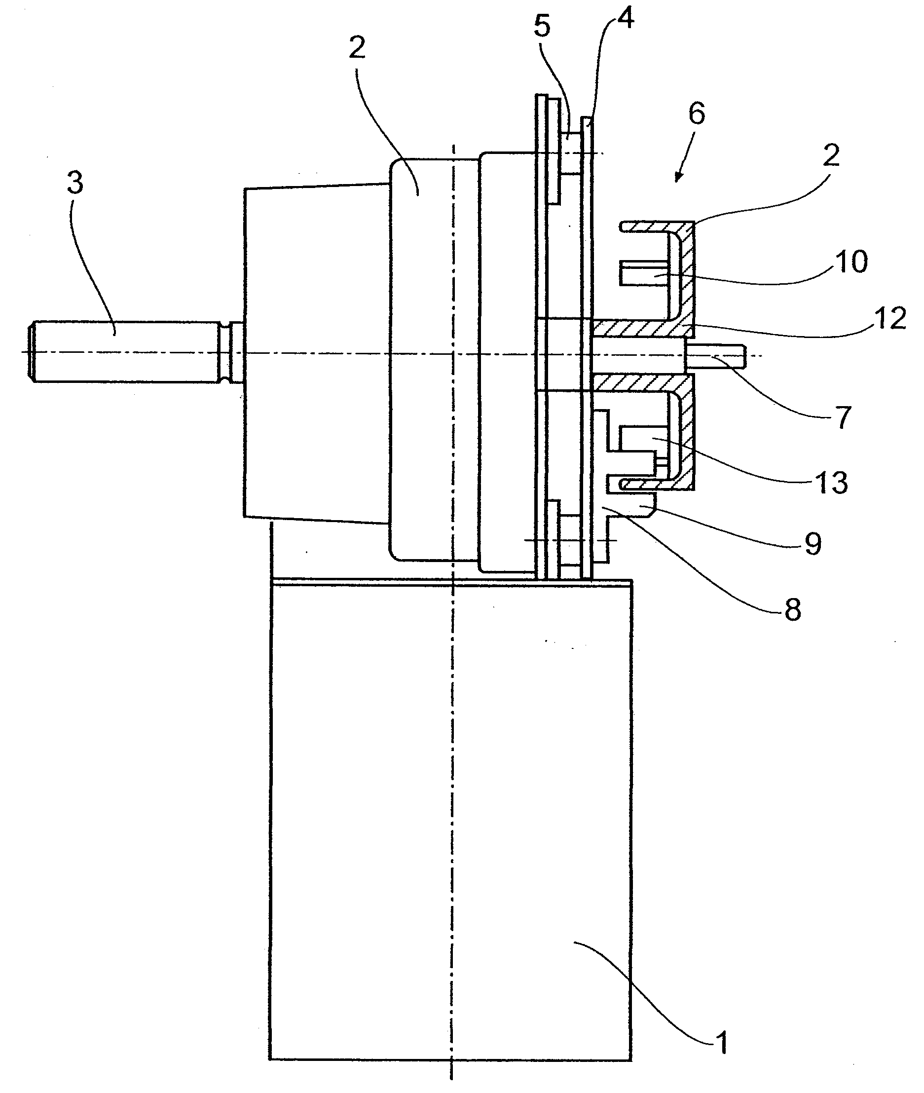
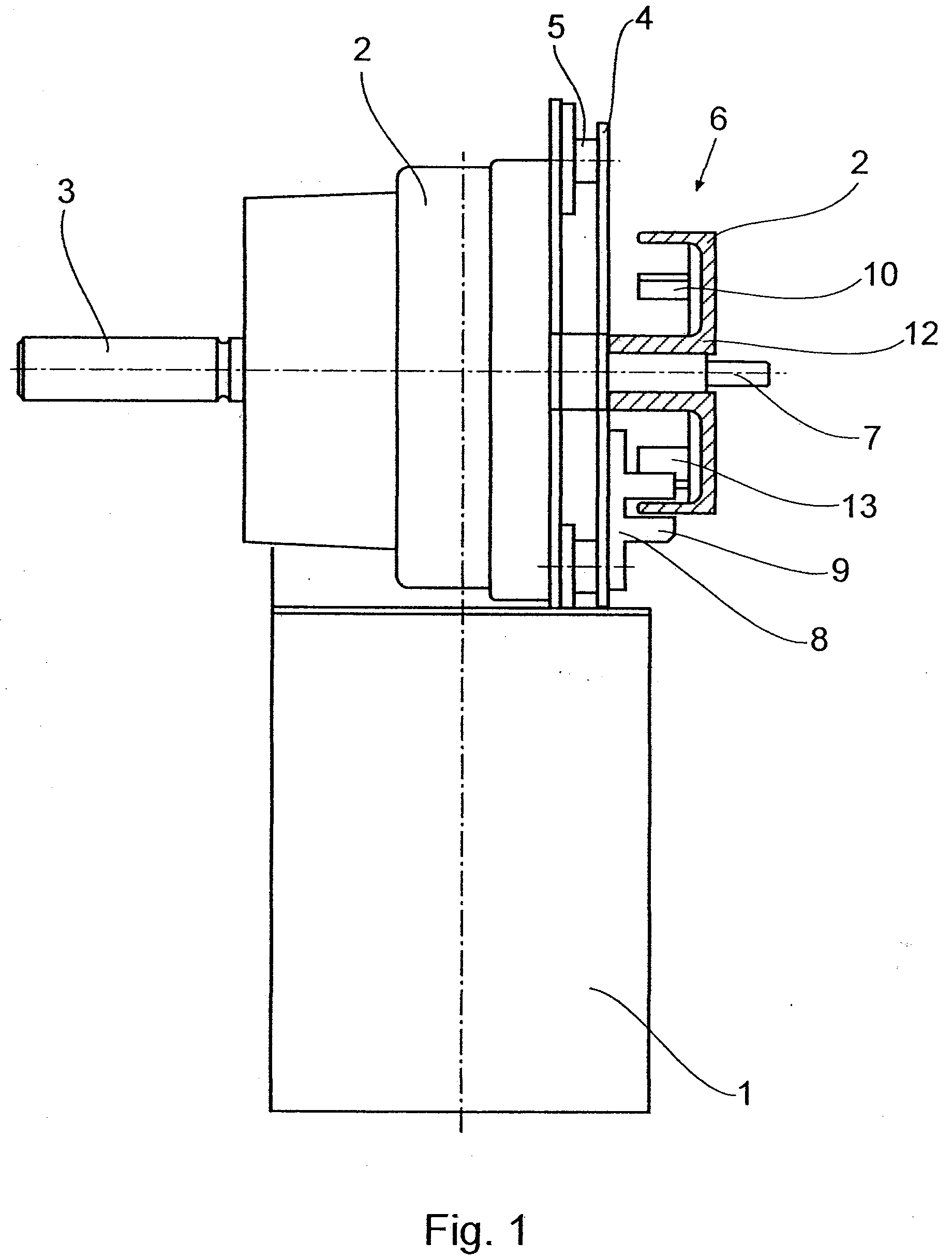
[0039]A drive unit is depicted in FIG. 1, which comprises a drive motor 1, which is connected to a gear 2 which includes a drive shaft being equipped with two opposed drive shaft ends 3, 7. The drive shaft end 3 serves for driving a non-illustrated pinion or drive wheel, and the drive shaft end 7 is directly connected to an information carrier 6. The embodiment of FIG. 1, where the drive shaft ends 3 and 7 are provided on each side of the gear 2 and are not extending in axial direction of the drive motor 1, is not mandatory. Instead, any other suitable arrangement can be chosen.

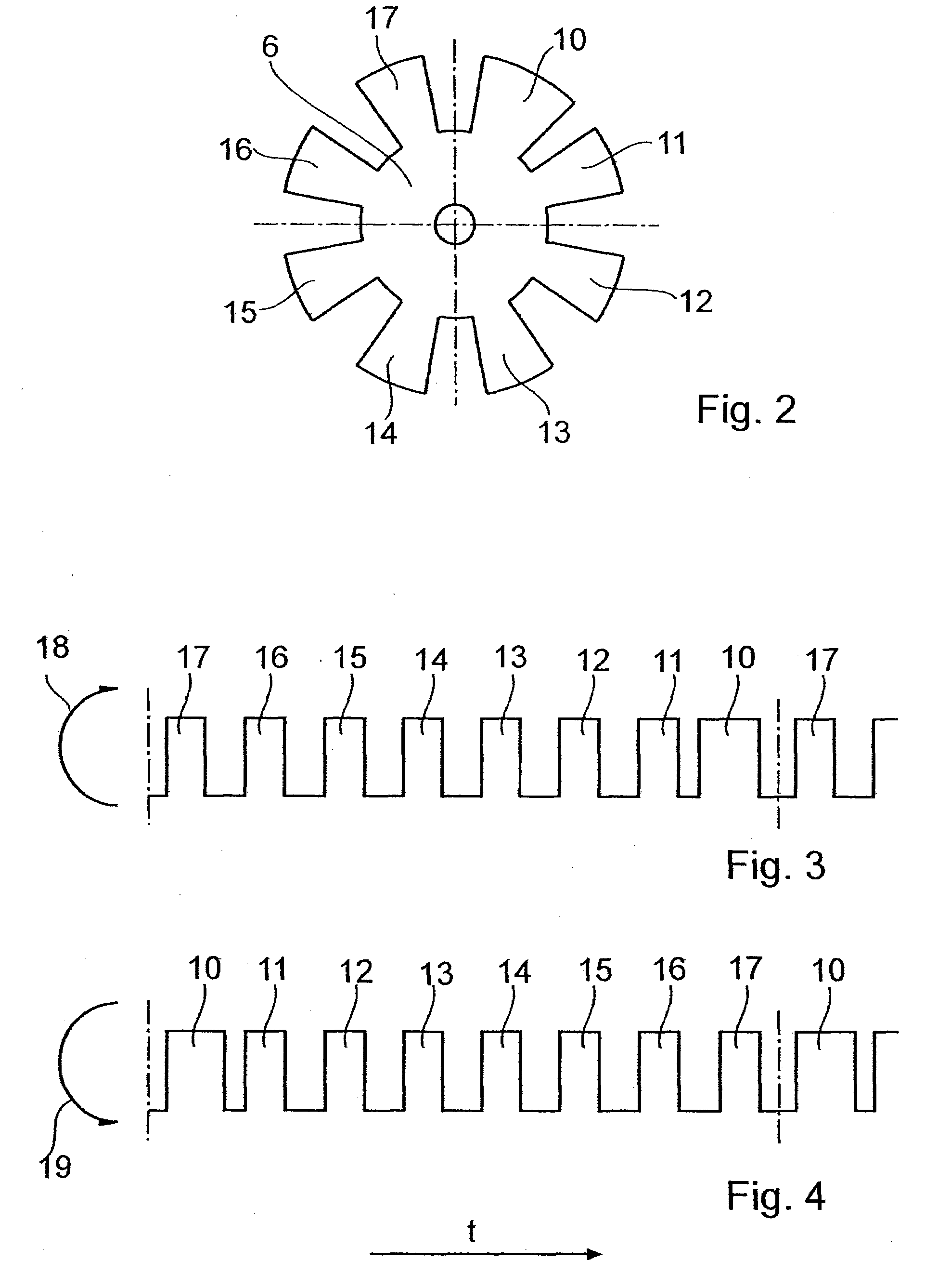
[0040]The information carrier 6 is formed as a bell or cup, and information elements 10 to 17 are distributed about the circumference thereof projecting from a bottom of the information carrier 6. These information elements 10 to 17 cooperate with a sampling system 8 in the form of a fork-shaped light barrier, such that the information elements 10 to 17 pass between the two legs 9 of the sampling system 8 whi...


PUM


Abstract

A drive unit for a door or a gate includes an electric motor, a detection unit for detecting the position of the door or gate, the detection unit being coupled to the motor and providing an identical pulse sequence with every rotation of the motor, wherein the duration of one pulse in the sequence is different from the duration of the other pulses in the sequence, which are equal. All detected pulses are stored in a non-volatile memory. The drive unit includes an electronic control and regulating circuit including an output stage for the electric motor and at least one memory, in which an operational program is stored providing a programmable learning procedure for an opening and closing movement of the door or gate based on the pulses provided by the detection unit.

Description

CROSS-REFERENCE TO RELATED APPLICATIONS[0001]This application is a divisional of U.S. patent application Ser. No. 11 / 501,591 which was filed with the U.S. Patent and Trademark Office on Aug. 9, 2006 which claims priority from German Application No. 10 2005 039 532.5 filed Aug. 18, 2005. The entire disclosures of both of these applications are expressly incorporated herein by reference.BACKGROUND OF THE INVENTION[0002]1. Field of the Invention[0003]The invention relates to a drive unit for a door or a gate, particularly a garage door, having an electric motor.[0004]2. Description of the Related Art[0005]EP 0 500 984 B1 describes a drive unit for a garage door, which is equipped with four terminal limit switches. In this case, the drive shaft protruding from the gear is provided with a pinion, which, on the one hand, drives the revolving chain and, on the other hand, is designed such that a bevel gear pinion simultaneously drives a terminal limit switch unit. In this case, the termina...

Claims


Application Information

Patent Timeline
Patent Type & Authority Applications(United States)
IPC IPC(8): E05F15/00
CPCE05Y2400/30E05Y2400/456E05Y2600/454E05Y2900/106E05F15/668E05Y2800/00E05Y2900/00E05F15/603E05Y2400/337
Inventor THEILE, ULRICHDIETZ, CHRISTIAN
Owner NOVOFERM TORMATIC GMBH
Why Eureka
Try Eureka