Solenoid valve and hydraulic braking system for vehicle

A hydraulic brake and solenoid valve technology, applied in the field of solenoid valves, can solve problems such as functional reliability or functional availability not reaching the required level, and achieve the effects of reduced energy consumption, low leakage, and low additional costs

Active Publication Date: 2019-06-07
ROBERT BOSCH GMBH
View PDF10 Cites 9 Cited by
  • Summary
  • Abstract
  • Description
  • Claims
  • Application Information

AI Technical Summary

Problems solved by technology

In addition, the functional reliability or functional availability is not to the required degree if the function is only implemented by active energization

Method used


Image

  • Solenoid valve and hydraulic braking system for vehicle
  • Solenoid valve and hydraulic braking system for vehicle
  • Solenoid valve and hydraulic braking system for vehicle

Examples


Embodiment Construction

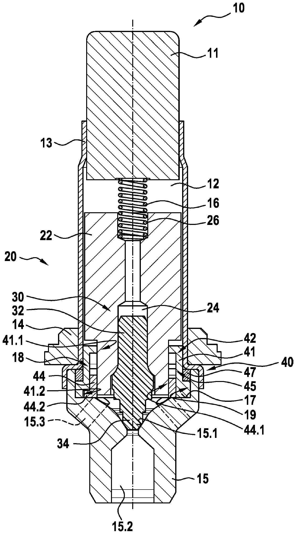
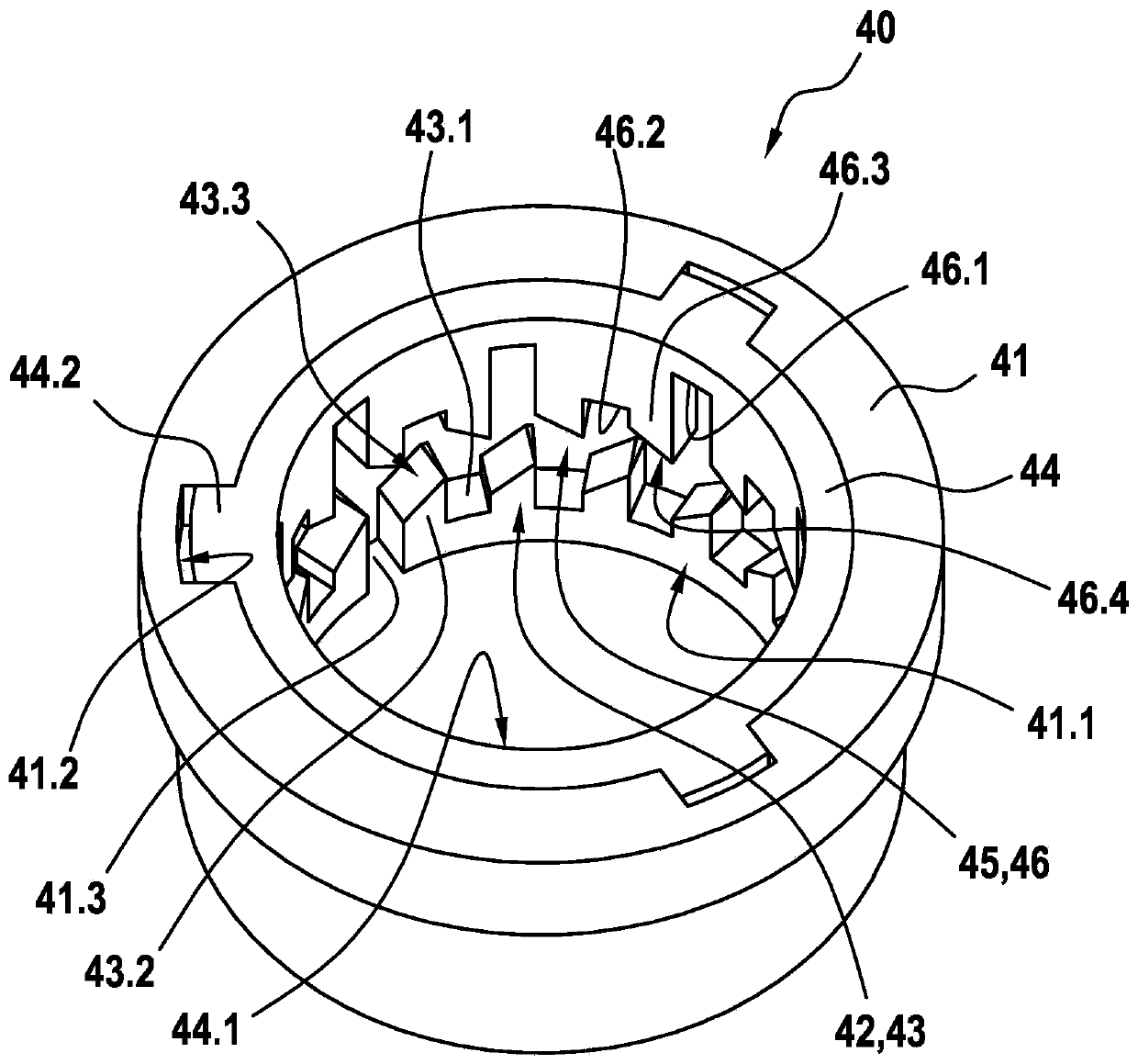
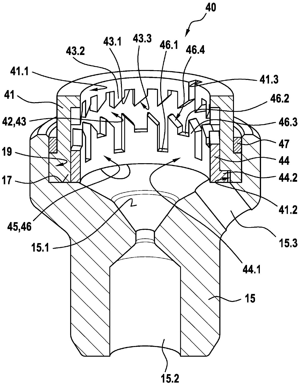
[0024] as by Figure 1 to Figure 11 As can be seen, the shown exemplary embodiment of a solenoid valve 10 according to the invention for a hydraulic brake system 1 comprises a magnet assembly, not further shown, a pole core 11 , a guide sleeve 13 connected to the pole core 11 , a valve armature 20 guided axially movable in the guide sleeve 13, and a valve body 15 connected to the guide sleeve 13 and having a valve seat 15.1, wherein the valve armature can be overcome by the magnetic force generated by the magnet assembly. Driven by the force of the position spring 16 or driven by the force of the return spring 16 and move the tappet 30 with the closing element 34 in the axial direction, the valve seat is arranged in at least one first flow opening 15.2 and at least one second flow opening 15.3, wherein the tappet 30 is fixedly connected with the valve armature 20 . In this case, the valve body 15 has a receiving region 19 which at least partially accommodates the guide assemb...


PUM


Abstract

The invention relates to a solenoid valve (10) for a hydraulic braking system, comprising: a magnetic assembly; a pole core (11); a guide sleeve (13) joined to the pole core (11); a valve armature (20) running axially movably within the guide sleeve (13), the armature being drivable in opposition to a force of a restoring spring (16) by means of a magnetic force produced by the magnetic assembly,or being drivable by the force of the restoring spring (16), and said armature moving a plunger (30) comprising a closing element (34); and a valve body (15) connected to the guide sleeve (13) and comprising a valve seat (15.1) that is located between at least one first flow opening (15.2) and at least one second flow opening (15.3), the plunger (30) being fixedly connected to the valve armature (20). The invention also relates to a hydraulic braking system comprising a solenoid valve (10) of this type. The valve body (15) has a receiving region (19) which at least partially accommodates a guide assembly (40), the valve armature (20) running axially through at least one through-opening (41.1, 44.1) of the guide assembly (40), a mechanical detent device (18) being formed between the guide assembly (40) and the valve armature (20), the detent device releasing the valve armature (20) when the latter is in a de-energised closed position, such that the restoring spring (16) drives the valvearmature (20) and pushes the closing element (34) sealingly into the valve seat (15.1) to produce a sealing function, and said detent device fixes the valve armature (20) in a de-energised open position against the force of the restoring spring (16) in an axial detent position, such that the closing element (34) is raised from the valve seat (15.1).

Description

technical field [0001] The invention relates to a solenoid valve for a hydraulic brake system of the type according to independent claim 1 . The object of the invention is also a hydraulic braking system for vehicles with such a solenoid valve. Background technique [0002] Hydraulic braking systems for vehicles are known from the prior art with a master brake cylinder, a hydraulic unit and a plurality of wheel brakes, which hydraulic braking systems include various safety systems, such as anti-lock braking systems (ABS), Electronic Stability Program (ESP), etc., and different safety functions can be implemented, such as anti-lock function, anti-skid regulation (ASR) and so on. The hydraulic unit can be used in the anti-lock brake system (ABS) or in the anti-slip control system (ASR system) or in the electronic stability program system (ESP system) to carry out control and / or for the pressure build-up or pressure relief in the corresponding wheel brakes conditioning proces...

Claims


Application Information

Patent Timeline
Patent Type & Authority Applications(China)
IPC IPC(8): B60T8/36F16K31/06
CPCB60T8/363B60T8/4872F16K31/5245F16K31/56F16K31/0655B60T13/62B60T13/686B60T15/028B60T2270/10B60T2270/20B60T2270/30B60T2270/404F16K31/003
Inventor W·斯塔尔M·亚姆布罗西M·埃森劳尔E·库尔茨D·克拉策
Owner ROBERT BOSCH GMBH
Why Eureka
Try Eureka