Tool bit structure

A technology of cutter head and cutter seat, applied in the field of cutter head structure, can solve the problems of complicated cutter head structure and troublesome installation, and achieve the effect of low cost, convenient installation and few parts

Active Publication Date: 2019-06-11
WENZHOU RUNWE ELECTRICAL APPLIANCE
View PDF7 Cites 8 Cited by
  • Summary
  • Abstract
  • Description
  • Claims
  • Application Information

AI Technical Summary

Problems solved by technology

[0006] In order to overcome the deficiencies of the background technology, the present invention provides a cutter head structure, which solves the problems of complicated structure and troublesome installation of the existing cutter head

Method used


Image

  • Tool bit structure
  • Tool bit structure
  • Tool bit structure

Examples


Embodiment Construction

[0026] Embodiments of the present invention will be further described below in conjunction with accompanying drawings:

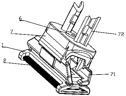
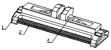
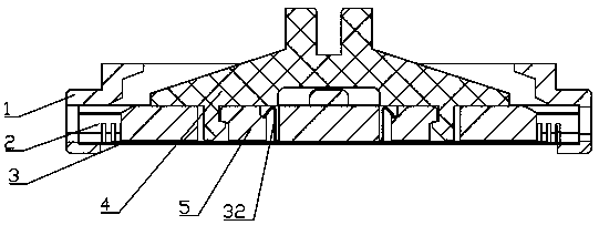
[0027] As shown in the figure, a cutter head structure includes a cutter seat 1 , a static cutter 2 , a movable cutter 3 , a support frame 4 , and a movable cutter holder 5 .

[0028] The static knife 2 is fixedly installed on the knife seat 1, and slotted holes 21 are evenly arranged on both sides of the stationary knife 2; the support frame 4 is slidably arranged on the knife seat 1, and is connected with a drive that drives it to reciprocate and slide. Mechanism 6; the moving knife rest 5 is fixedly connected with the support frame 3, and can move synchronously with the support frame 3; the moving knife 3 is installed on the moving knife rest 5, and fits with the static knife 2, and the moving knife 3 There are moving blades 31 corresponding to the slots 21 on both sides.

[0029] The movable knife 3 is provided with two elastic pieces 32, and the elasti...


PUM


Abstract

The invention provides a tool bit structure. The tool bit structure is characterized in that at least two elastic pieces are arranged on a movable knife, the elastic pieces and the movable knife are of an integrated structure, and the elastic pieces comprise supporting parts and elastic parts on the tops of the supporting parts; and the elastic pieces penetrate through a movable knife rest, and the elastic parts of the elastic pieces abut against a supporting frame and the movable knife rest. The tool bit structure has the beneficial effects that the movable knife and the movable knife rest can be connected and mounted through the elastic pieces, meanwhile, the elastic parts of the elastic pieces can cooperate with the supporting frame, elastic pressure is provided for the movable knife, the movable knife is elastically attached to a fixed knife, compared with an existing conventional tool bit structure, the structures of a set of springs or elastic pieces are omitted, parts are fewer,the cost is lower, and mounting is more convenient.

Description

technical field [0001] The invention relates to a hair trimming device, in particular to a cutter head structure. Background technique [0002] A razor is a tool for shaving beards, mostly used by adult men. [0003] According to the structure of the cutter head, the razor can be divided into a rotary cutter head and a reciprocating cutter head. [0004] The reciprocating cutter head usually includes a knife seat, a static knife, a moving knife, a support frame, and a moving knife frame. The static knife is fixed on the knife seat, and the moving knife is fixed on the moving knife frame. The spring or shrapnel drives the moving knife to be attached to the static knife through the spring or shrapnel. At the same time, the support frame is connected to the driving mechanism. The driving mechanism drives the moving knife through the support frame, spring, and moving knife frame to realize linear reciprocating action and realize the hair cutting function. [0005] However, the...

Claims


Application Information

Patent Timeline
Patent Type & Authority Applications(China)
IPC IPC(8): B26B19/04
CPCB26B19/04
Inventor 俞光美
Owner WENZHOU RUNWE ELECTRICAL APPLIANCE
Why Eureka
Try Eureka