Al technical title is built by PatSnap Al team. It summarizes the technical point description of the patent document.
A combined cooling and heating technology and heat pump technology, which is applied in the field of heat pump cooling and heating equipment, can solve the problems of heavy snowfall, snow accumulation on the top of the heat pump, and intense dust in the heat dissipation holes, etc.
Active Publication Date: 2019-06-11
SHANDONG MODERN LION AIR CONDITIONING EQUIP
View PDF8 Cites 1 Cited by
Summary
Abstract
Description
Claims
Application Information
AI Technical Summary
This helps you quickly interpret patents by identifying the three key elements:
Problems solved by technology
Method used
Benefits of technology
Problems solved by technology
[0003] Existing heat pump combined cooling and heating equipment is generally installed in the northern region, but due to the high probability of snowfall and the large amount of snowfall in the northern region, it is easy to cause snow accumulation on the top of the heat pump installed outdoors, which will block the intake pipe and affect the heat dissipation efficiency of the heat pump , and the melting of snow water is easy to rust the heat pump shell. Since the heat pump is installed outdoors, the dust in the outdoor environment is easy to be intense in the inner cavity of the heat dissipation hole, which is not easy to clean
Method used
Image
Click on the blue label to locate the original text in one second.
Reading with bidirectional positioning of images and text.
Examples
Embodiment Construction
[0021] The following will clearly and completely describe the technical solutions in the embodiments of the present invention with reference to the accompanying drawings in the embodiments of the present invention. Obviously, the described embodiments are only some of the embodiments of the present invention, not all of them. Based on the embodiments of the present invention, all other embodiments obtained by persons of ordinary skill in the art without making creative efforts belong to the protection scope of the present invention.
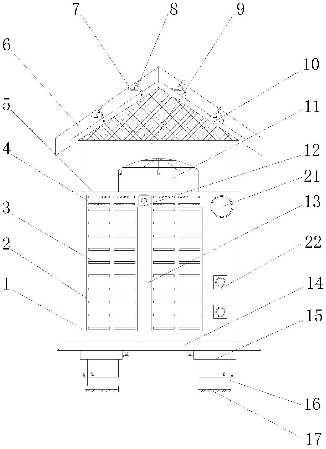
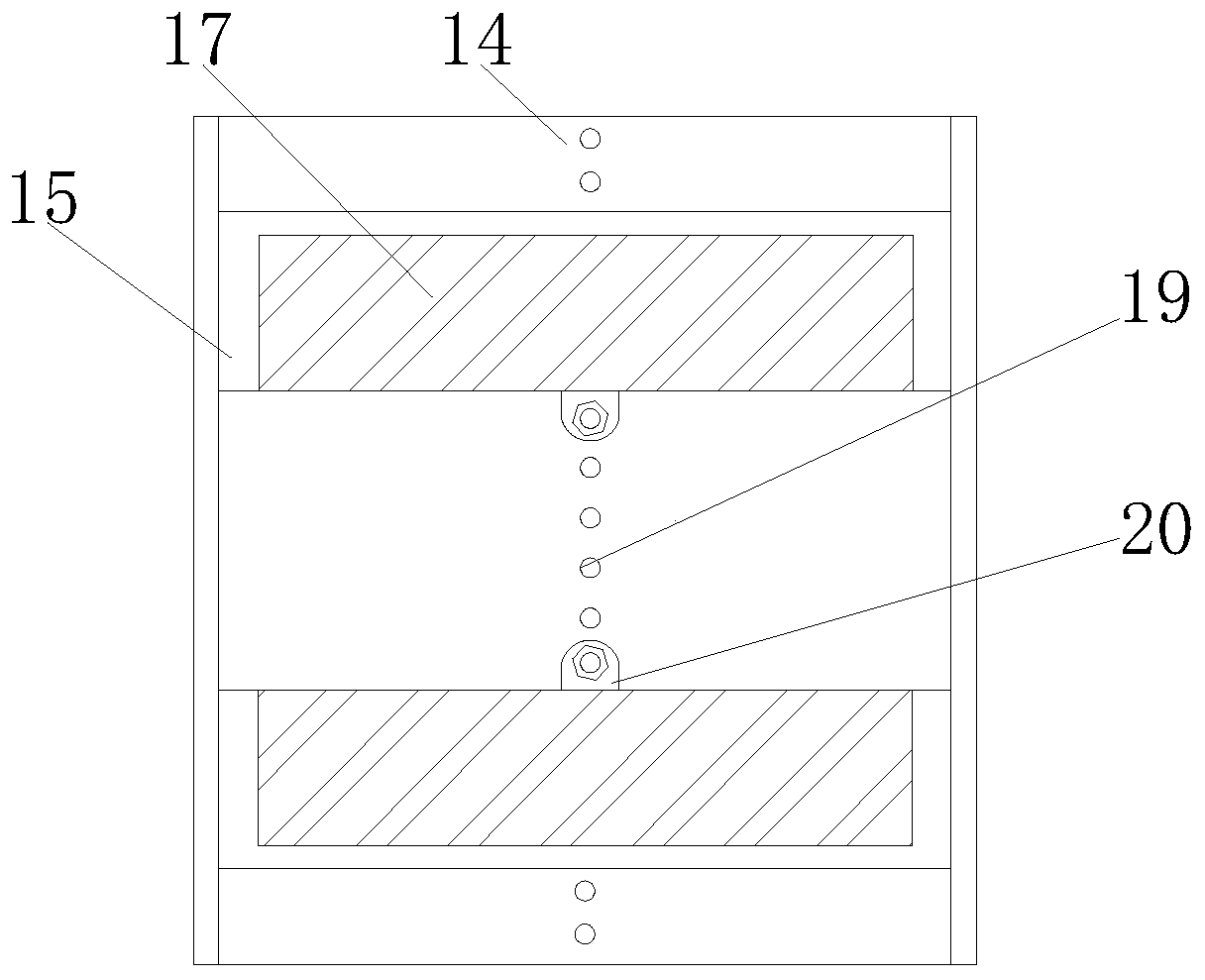
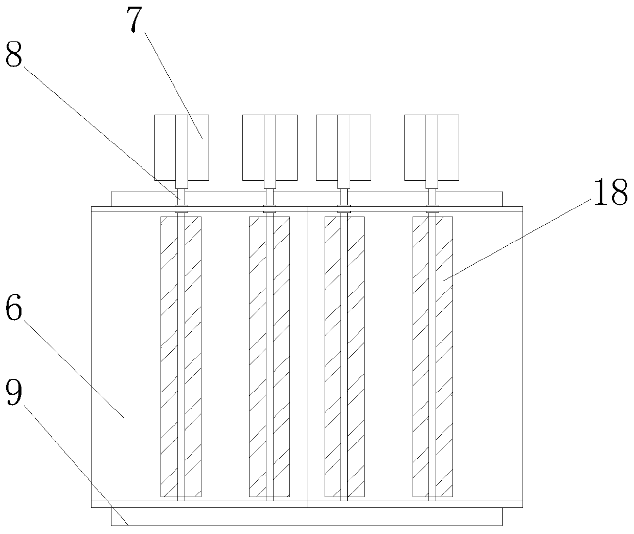
[0022] see Figure 1-4 As shown, a heat pump combined cooling and heating equipment includes an installation mechanism, an overall mechanism, a heat dissipation mechanism for dissipating heat from the overall mechanism, and a snow protection mechanism for protecting the overall mechanism; wherein, the installation mechanism includes Bottom support plate 14, bottom positioning block 15, inserting plate 16, support plate 17, positioning hole 19 and...
PUM
Abstract
The invention belongs to the technical field of pumps, and particularly relates to heat pump cooling and heating co-supply equipment. The heat pump cooling and heating co-supply equipment comprises aheat pump outer shell, condenser heat dissipation grooves, heat dissipation holes, rotating cylinders, dust sticking blocks, a triangular groove plate, a wind wheel, a rotating rod, snow protection frame, shielding meshes, an air inlet pipe, a dust removal sliding block, a sliding groove, a bottom supporting plate, a bottom positioning block, an inserting plate, a supporting plate, pushing pieces,positioning holes, connecting pieces, a pressure gauge and pipeline connecting holes. According to the heat pump cooling and heating co-supply equipment, the triangular groove plate is arranged at the top end of the heat pump outer shell, the pushing pieces are rotatably connected to an inner cavity of the triangular groove plate, a windmill is fixedly connected to the end part of the rotating rod, the snow falling from the top can be accumulated on the surface of the triangular groove plate through the triangular groove plate in snowfall weather, and the wind wheel is driven to rotate through the airflow in the air, and then the rotating rod is driven to rotate, so that the function of the pushing pieces quickly removing the accumulated snow on the surface of the triangular groove plateis realized; and the blockage of the air inlet pipe, the corrosion of the top end of the heat pump outer shell and the influence on the overall heat dissipation efficiency due to the fact that snow isaccumulated on the surface of the top end of the heat pump outer shell are prevented.
Description
technical field [0001] The invention belongs to the technical field of pumps, in particular to a heat pump combined cooling and heating equipment. Background technique [0002] A heat pump is a high-efficiency energy-saving device that makes full use of low-grade heat energy. Heat can be spontaneously transferred from a high-temperature object to a low-temperature object, but it cannot be carried out in the opposite direction spontaneously. The working principle of the heat pump is to force heat from a low temperature to The mechanical device in which objects flow to high-temperature objects consumes only a small amount of reverse cycle net work to obtain a large amount of heat supply, and can effectively utilize low-grade heat energy that is difficult to apply to achieve energy-saving purposes. [0003] Existing heat pump combined cooling and heating equipment is generally installed in the northern region, but due to the high probability of snowfall and the large amount of ...
Claims
Application Information
Patent Timeline
Application Date:The date an application was filed.
Publication Date:The date a patent or application was officially published.
First Publication Date:The earliest publication date of a patent with the same application number.
Issue Date:Publication date of the patent grant document.
PCT Entry Date:The Entry date of PCT National Phase.
Estimated Expiry Date:The statutory expiry date of a patent right according to the Patent Law, and it is the longest term of protection that the patent right can achieve without the termination of the patent right due to other reasons(Term extension factor has been taken into account ).
Invalid Date:Actual expiry date is based on effective date or publication date of legal transaction data of invalid patent.