Method for constructing real-time visual fluid in a complex three-dimensional pipe network

A three-dimensional pipe network and fluid technology, which is used in 3D modeling, image data processing, special data processing applications, etc., can solve problems such as narrow internal space and inability to complete real-time fluid simulation, and achieve the effect of reducing the amount of calculation.

Active Publication Date: 2019-06-11
BEIJING INSTITUTE OF PETROCHEMICAL TECHNOLOGY
View PDF2 Cites 5 Cited by
  • Summary
  • Abstract
  • Description
  • Claims
  • Application Information

AI Technical Summary

Problems solved by technology

In a large-scale complex three-dimensional pipe network scene, due to the vertical three-dimensional distribution of the pipe network and the narrow internal space of many branch paths, the fluid in the pipe network is scattered and not distributed on the same plane, and the boundary problem with

Method used


Image

  • Method for constructing real-time visual fluid in a complex three-dimensional pipe network
  • Method for constructing real-time visual fluid in a complex three-dimensional pipe network
  • Method for constructing real-time visual fluid in a complex three-dimensional pipe network

Examples


specific Embodiment approach

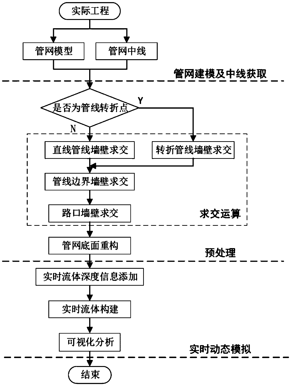
[0024] The method for constructing a real-time visualized fluid in a complex three-dimensional pipe network according to the present invention is preferably implemented in the following manner:

[0025] include:

[0026] Step A: According to the actual project, use the special midpoint extraction method to obtain the three-dimensional pipe network model and the pipe network centerline data;

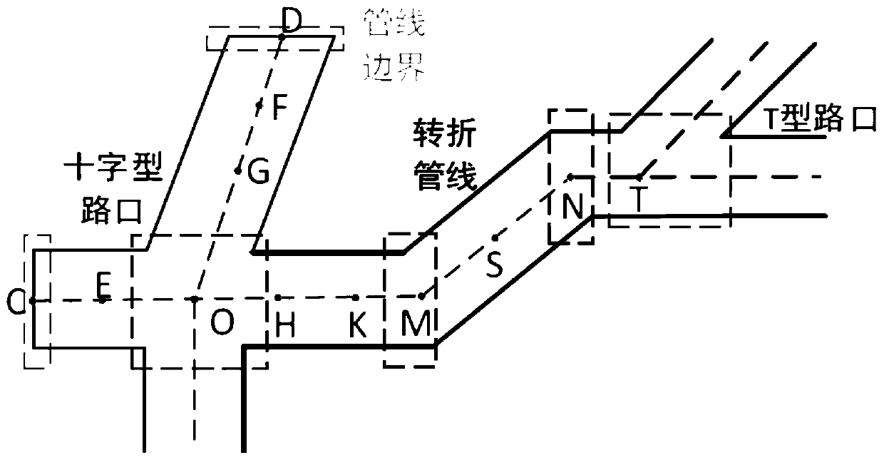
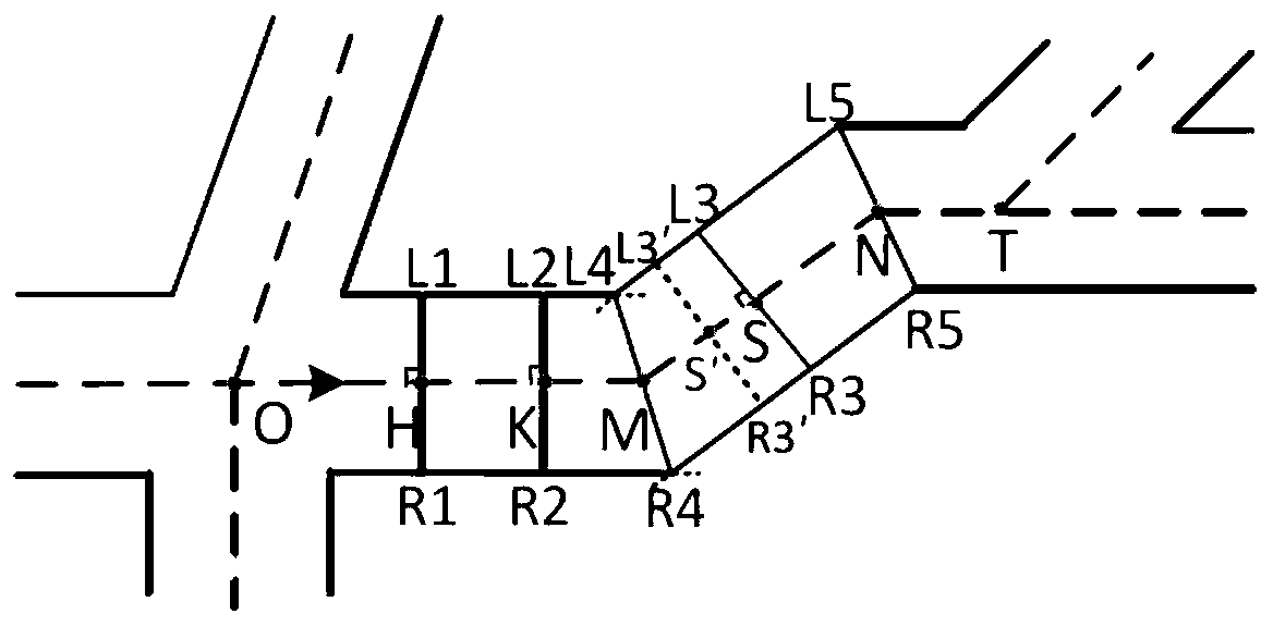
[0027] Step B: Use the method of intersecting the vertical line of the centerline of the pipeline network with the pipeline wall, and according to different types of pipelines and intersections, respectively calculate the corresponding wall intersection points at each midpoint, and use the wall intersection points to reconstruct the bottom surface of the pipeline network;

[0028] Step C: Using the reconstructed bottom surface of the pipe network, combined with the characteristics of the pipe network model and the real-time fluid depth information obtained from numerical simulation or sen...

Embodiment 1

[0082] Take the simulation of water inrush in a roadway when a water inrush accident occurred in a coal mine in Hebei as an example.

[0083] Step 101: use 3ds Max software to build the roadway three-dimensional model ( Figure 8 ), and mark the midpoints of all boundaries and intersections in the model as the starting point and end point of the roadway path. The complete centerline of the roadway can be obtained ( Figure 9 ), use the format conversion tool to convert the roadway and midline data in .3ds format into .txt format, and import the roadway and midpoint into computer memory in the form of three-dimensional coordinates with topology.

[0084] Step 102: For each path in the roadway according to the midline data, judge whether this point is a pipeline turning point starting from the second point in the order of midpoints, and turn to step 103 for non-turning points, and turn to step 104 for turning points until the countdown of the path until the second point.

[0...


PUM


Abstract

The invention discloses a method for constructing real-time visual fluid in a complex three-dimensional pipe network, which comprises the following steps of: analyzing and concluding various pipelinesand intersections in the complex three-dimensional pipe network, obtaining pipe network center line data through pipe network modeling and center line acquisition, and determining the types of the pipelines and the intersections; For various pipelines and intersections, methods of intersection operation, pipe network bottom surface reconstruction and the like are adopted to establish a fluid surface model so as to reduce the real-time fluid modeling calculation amount. The fluid surface and the fluid depth are updated in real time based on real-time fluid depth information obtained through asensor network or numerical simulation and the pipe network model category, and real-time fluid modeling is achieved; And finally realizing real-time visualization of the fluid under the complex three-dimensional pipe network scene by adopting a rendering technology. Taking mine water inrush as an example, the feasibility of the method is verified, and visual analysis is carried out. The problem that real-time visualization of fluid in a complex three-dimensional pipe network is difficult to achieve is solved.

Description

technical field [0001] The invention relates to a real-time fluid visualization technology in a complex three-dimensional pipe network, in particular to a method for constructing a real-time visualized fluid in a complex three-dimensional pipe network. Background technique [0002] Complex three-dimensional pipeline network is an important infrastructure in the survival and development of cities, such as common oil and gas pipelines, mine tunnels, urban subway tracks, underground water pipelines, etc., are closely related to people's daily life and work. Real-time simulation of the fluid movement state in the three-dimensional pipe network can effectively help people monitor the material transportation state in the pipe network, and guide people to avoid risks in time during disaster prevention and avoidance (such as water inrush from roadways and tracks); Fluid simulation can effectively simulate underground underground rivers and surface rivers in 3D geological simulation;...

Claims


Application Information

Patent Timeline
IPC IPC(8): G06F17/50G06T17/00
CPCY02A10/40
Inventor 张越徐华
Owner BEIJING INSTITUTE OF PETROCHEMICAL TECHNOLOGY
Why Eureka
Try Eureka