Multicoaxial cable
A technology of multi-core cables and wires, applied in cables, communication cables, insulated cables, etc., to achieve the effect of improving bending resistance
- Summary
- Abstract
- Description
- Claims
- Application Information
AI Technical Summary
Problems solved by technology
Method used
Image

Examples
no. 1 approach
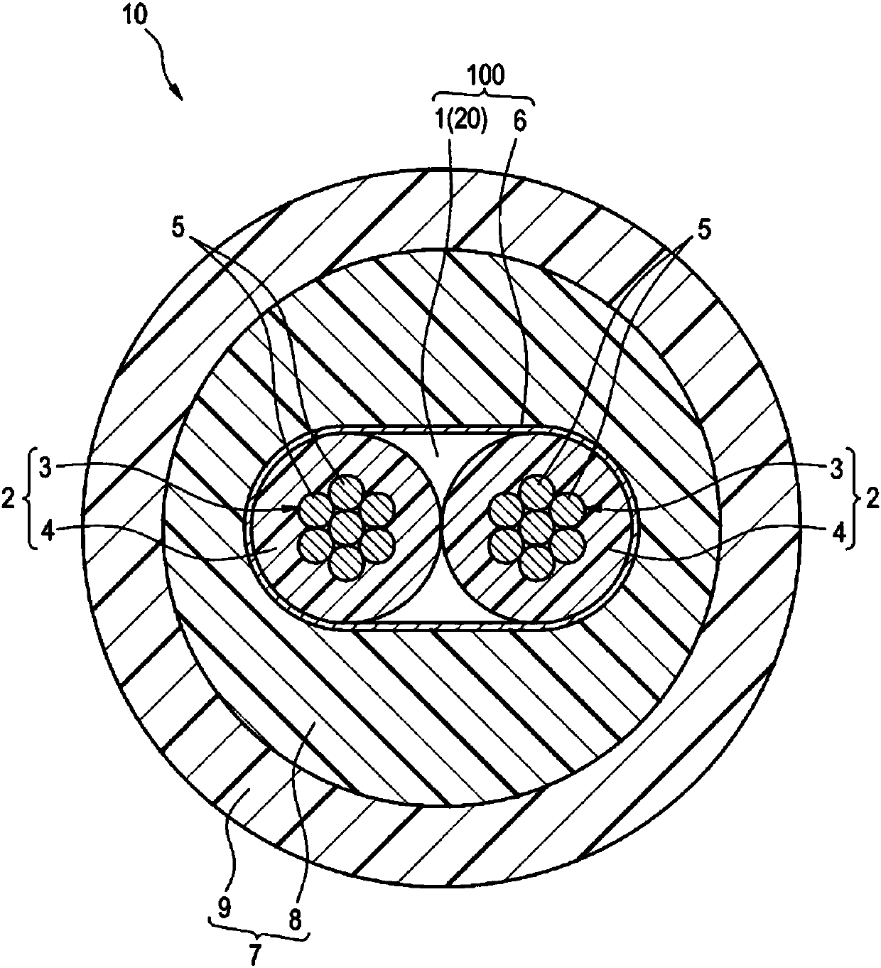
[0080] figure 1 It is a sectional view showing the structure of the electrically insulating cable 10 (an example of a multi-core cable) according to the first embodiment of the present invention. The electrically insulated cable 10 is used, for example, in an electric brake mounted on a vehicle, and can be used as a cable for supplying electric power to a motor that drives a brake caliper. The electrically insulated cable 10 is used in particular in an electric parking brake (Electro Mechanical Parking Brake: EPB).
[0081] Such as figure 1 As shown, the electrically insulated cable 10 has: a core wire 1, a tape 6 (an example of a tape member) wound around the core wire 1, and a sheath 7 (sheath 7) covering the outer periphery of the tape 6 wound around the core wire 1. an example of ). The outer diameter of the electrically insulated cable 10 of this example is in the range of 6-12 mm, preferably in the range of 7.0-10.5 mm.
[0082] The core wire 1 is formed by twisting ...
no. 2 approach
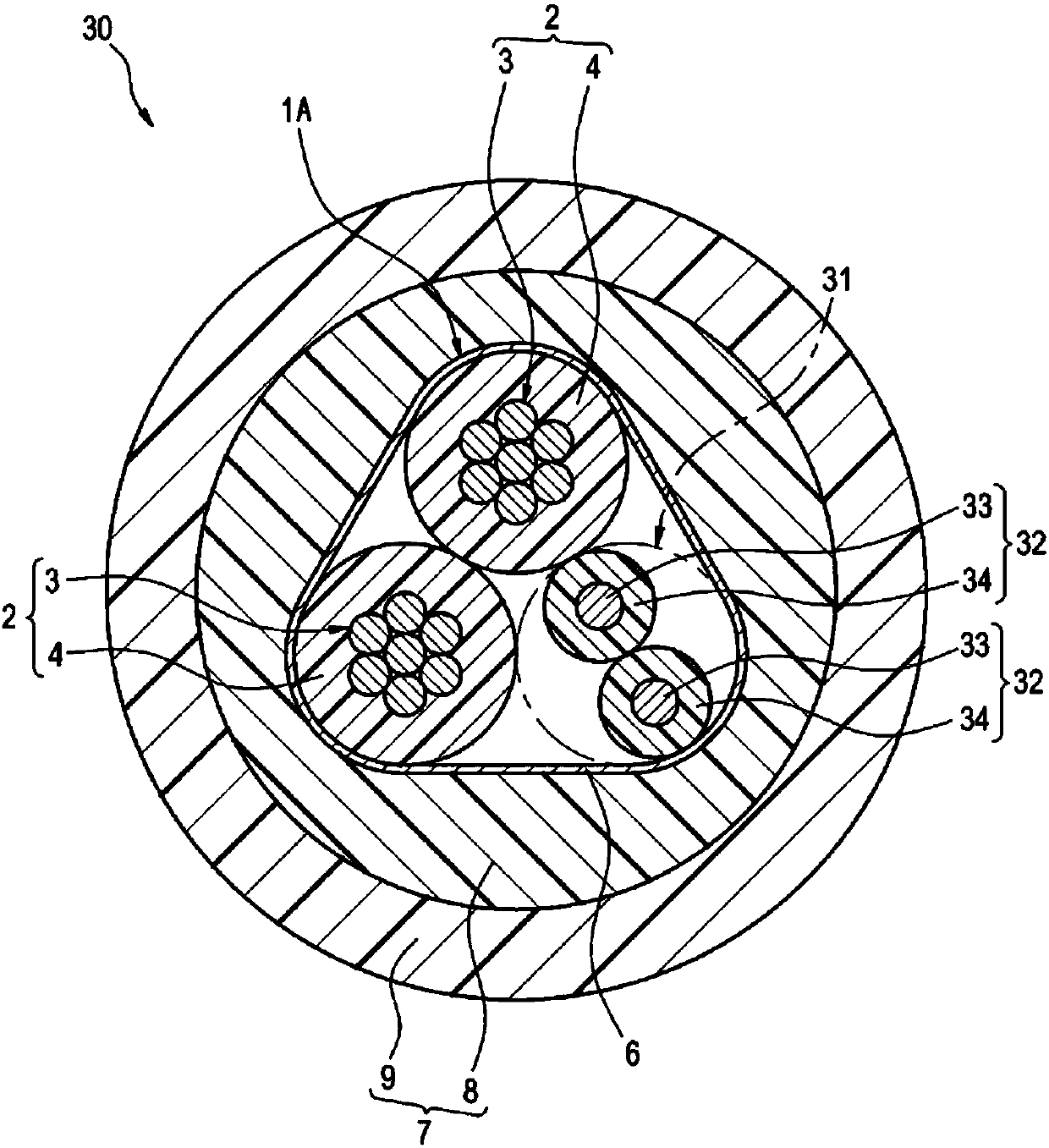
[0105] Below, refer to image 3 , the second embodiment of the present invention will be described. In addition, the same code|symbol is attached|subjected to the part of the same structure as 1st Embodiment, and description is abbreviate|omitted. image 3 A cross section of an electrically insulating cable 30 according to the second embodiment is shown. The electrically insulated cable 30 of the present embodiment can be used to transmit electric signals from a wheel speed sensor, for example, in addition to supplying electric power to an electric brake (for example, an electromechanical parking brake). In addition, the electrically insulated cable 30 can be used for transmitting signals from other devices to a vehicle ECU (Electronic Control Unit) and for transmitting signals from a vehicle ECU to devices.
[0106] Such as image 3 As shown, the difference between the electrically insulated cable 30 of this example and the first embodiment is that, in addition to the two ...
no. 3 approach
[0113] Below, refer to Figure 4 , the third embodiment of the present invention will be described. In addition, the same code|symbol is attached|subjected to the part of the same structure as 1st and 2nd embodiment, and description is abbreviate|omitted. Figure 4 A cross section of an electrically insulating cable 40 according to the third embodiment is shown.
[0114] Such as Figure 4 As shown, the difference between the electrically insulated cable 40 of this example and the second embodiment is that the core wire 1B has a subunit 41 (the third unit an example of ).
[0115] The subunit 41 is formed by twisting two insulated wires 42 (an example of a third insulated wire) each having a diameter smaller than that of the insulated wire 2 but substantially the same as each other. Each of the two insulated electric wires 42 is composed of a conductor 43 and an insulating layer 44 formed to cover the outer periphery of the conductor 43 . The structures of the conductor 43...
PUM
| Property | Measurement | Unit |
|---|---|---|
| Area | aaaaa | aaaaa |
| Outer diameter | aaaaa | aaaaa |
| Area | aaaaa | aaaaa |
Abstract
Description
Claims
Application Information
 - R&D
- Intellectual Property
- Life Sciences
- Materials
- Tech Scout
- Unparalleled Data Quality
- Higher Quality Content
- 60% Fewer Hallucinations
Browse by: Latest US Patents, China's latest patents, Technical Efficacy Thesaurus, Application Domain, Technology Topic, Popular Technical Reports.
© 2025 PatSnap. All rights reserved.Legal|Privacy policy|Modern Slavery Act Transparency Statement|Sitemap|About US| Contact US: help@patsnap.com